background image

21

Parking Brake Adjustment

WARNING: 

Never attempt to adjust the

brakes while the engine is running. Always
disengage PTO, move speed control lever
into neutral position, stop engine and remove
key to prevent unintended starting.

If the tractor does not come to a complete stop when 
the brake pedal is completely depressed, or if the 
tractor’s rear wheels can roll with the parking brake 
applied (and the hydrostatic bypass rod pulled out), the 
brake is in need of adjustment. The brake disc can be 
found on the right side of the transmission in the rear of 
the tractor. Adjust if necessary as follows:

NOTE: 

A replacement cotter pin (part no. 714-0111)

is needed to complete this adjustment. Have one on
hand before proceeding.

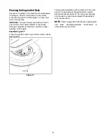
Looking at the transmission from the right side of 
the tractor, locate the compression spring and 
brake disc. See Figure 18.

Figure 18

Carefully remove the cotter pin from the crown nut 
on the right side of the brake assembly.

Using a feeler gauge, check the gap between the 
brake disc and the brake puck. Proper gap is .011". 

Tighten the crown nut until the proper gap is 
achieved.

Insert the replacement cotter pin into the crown nut.

Drag Link Adjustment

If the tractor turns tighter in one direction than the other, 
or if either the drag link and ball joint are being replaced 
due to damage or wear, the drag link may need to be 
adjusted. To do so, proceed as follows:

Place the steering wheel in position for straight- 
ahead travel.

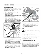
Remove the lock nut which secures the ball joint to 
the steering arm. See Figure 19.

Figure 19

Lift the ball joint out of the steering arm and re-
position both front tires for straight-ahead travel.

Loosen the jam nut (See Figure 19) and thread the 
ball joint either inward or outward until it aligns with 
the hole in the steering arm. 

Confirm that both the steering wheel and the front 
tires are still positioned for straight-ahead travel 
before reinserting the ball joint into the steering arm 
and securing it with the lock nut removed earlier.

Re-tighten the jam nut loosened earlier.

Crown Nut

NOTE: 

Rear, right wheel not shown for clarity

Brake Disc

Lock Nut

Steering Arm

Drag Link

Jam Nut

Ball Joint

Summary of Contents for 791

Page 1: ...fective working order by the operator In the State of California the above is required by law Section 4442 of the California Public Resources Code Other states may have similar laws Federal laws apply on federal lands A spark arrester for the muffler is available through your nearest engine authorized service dealer or contact the service department P O Box 361131 Cleveland Ohio 44136 9722 MTD LLC...

Page 2: ... unit you can seek help from the experts Choose from the options below Visit mtdproducts com for many useful suggestions Click on Customer Support button and you will get the four options reproduced here Click on the appropriate button and help is immediately available If you prefer to reach a Customer Support Representative please call 330 220 4MTD or 1 800 800 7310 The engine manufacturer is res...

Page 3: ...ersonal injury 7 Plan your mowing pattern to avoid discharge of material toward roads sidewalks bystanders and the like Also avoid discharging material against a wall or obstruction which may cause discharged material to ricochet back toward the operator 8 Always wear safety glasses or safety goggles during operation and while performing an adjustment or repair to protect your eyes Thrown objects ...

Page 4: ...op or shift while on the slope Tires may lose traction on slopes even though the brakes are functioning properly Always keep machine in gear when going down slopes to take advantage of engine braking action 4 Follow the manufacturer s recommendations for wheel weights or counterweights to improve stability 5 Use extra care with grass catchers or other attachments These can change the stability of ...

Page 5: ...g is complete Do not use a nozzle lock open device e Extinguish all cigarettes cigars pipes and other sources of ignition f Never fuel machine indoors g Never remove gas cap or add fuel while the engine is hot or running Allow engine to cool at least two minutes before refueling h Never over fill fuel tank Fill tank to no more than inch below bottom of filler neck to allow space for fuel expansion...

Page 6: ...mmediately with original equipment manufacturer s O E M parts only listed in this manual Use of parts which do not meet the original equipment specifications may lead to improper performance and compromise safety 12 Do not change the engine governor settings or over speed the engine The governor controls the maximum safe operating speed of the engine 13 Maintain or replace safety and instruction l...

Page 7: ...7 SECTION 2 SLOPE GAUGE 3IGHT AND HOLD THIS LEVEL WITH A VERTICAL TREE OR A CORNER OF A BUILDING OR A FENCE POST O L D A L O N G D O T T E D L I N E R E P R E S E N T S A S L O P E ...

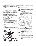
Page 8: ...heel cap over the center of the steering wheel and push downward until it clicks into place Figure 1 Shipping Brace Removal WARNING Make sure the riding mower s engine is off remove the ignition key and set the parking brake before removing the shipping brace Locate the shipping brace and accompanying warning tag found on the right side of the mower between the discharge chute and the cutting deck...

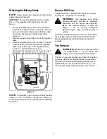
Page 9: ...attery as instructed on page 26 of this manual prior to operating the tractor Gas and Oil Fill up The gasoline tank is located under the hood and has a capacity of 1 1 2 gallons Do not overfill WARNING Use extreme care when handling gasoline Gasoline is extremely flammable and the vapors are explosive Never fuel machine indoors or while the engine is hot or running Extinguish cigarettes cigars pip...

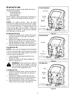
Page 10: ...h the two hex screws removed earlier See Figure 4 Quick Adjustment Seat NOTE If your seat was shipped mounted backwards on the seat pivot bracket pull out the tab found on the seat stop and hold it open while sliding the seat off the seat pivot bracket See Figure 5 1 Line up the plastic seat spacers with the slots in seat pivot bracket 2 Slide seat in until front seat spacer engages the seat stop ...

Page 11: ...T side of the tractor is observed from operator s position A Parking Brake Lever E Throttle Control Lever B brake Pedal F Ignition Switch Module C Speed Control Lever G Deck Lift Lever D Choke Control on models so equipped H PTO Blade Engage Lever PARK BRAKE P ON OFF FAST SLOW CHOKE E A G C B F H D ...

Page 12: ...ng the tractor to a complete stop NOTE The brake pedal must be depressed to start the engine Refer to Safety Interlock Switches on page 14 Parking Brake Lever To set the parking brake fully depress the brake pedal Move the parking brake lever all the way down and into the ON position Release the brake pedal to allow the parking brake to engage To release the parking brake depress the brake pedal a...

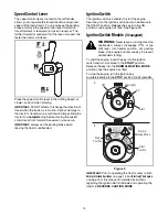
Page 13: ...tion switch is activated to start the engine Insert key into the ignition switch and turn clockwise to the START position Release the key into the ON position once engine has fired See Figure 9A Ignition Switch Module if equipped WARNING Never leave a running machine unattended Always disengage PTO move shift lever into neutral position set parking brake stop engine and remove key to prevent unint...

Page 14: ...for your safety and protection Reverse Caution Mode if equipped WARNING Use extreme caution while operating the tractor in the REVERSE CAUTION MODE Always look down and behind before and while backing Do not operate the tractor when children or others are around Stop the tractor immediately if someone enters the area The REVERSE CAUTION MODE position of the key switch module allows the tractor to ...

Page 15: ...te the choke control and place the throttle control in the FAST position NOTE Do NOT leave the throttle control in the CHOKE position while operating the tractor Doing so will result in a rich fuel mixture and cause the engine to run poorly Stopping the Engine WARNING If you strike a foreign object stop the engine disconnect the spark plug wire s and ground against the engine Thoroughly inspect th...

Page 16: ...ns when driving on a slope If a turn must be made turn down the slope Turning up a slope greatly increases the chance of a roll over Avoid stopping when driving up a slope If it is necessary to stop while driving up a slope start up smoothly and carefully to reduce the possibility of flipping the tractor over backward Using the Deck Lift Lever To raise the cutting deck move the deck lift lever to ...

Page 17: ...eck and not be mulched effectively Maintain a slow ground speed to allow the grass clippings more time to effectively be mulched Always position the throttle control lever in the FAST rabbit position and allow it to remain there while mowing Failing to keep the engine at full throttle places strain on the tractor s engine and does not allow the blades to properly mulch grass NOTE Do NOT remove the...

Page 18: ...upported by a stabilizer bar that can adjusted to level the deck from front to rear The front of the deck should be between 1 4 inch and 3 8 inch lower than the rear of the deck Adjust if necessary as follows With the tractor parked on a firm level surface place the deck lift lever in the top notch highest position and rotate the blade nearest the discharge chute so that it is parallel with the tr...

Page 19: ...e ground and the distance from the outside of the right blade tip to the ground Both measurements taken should be equal If they re not proceed to the next step Loosen but do NOT remove the hex screw on the left deck hanger bracket See Figure 14 Figure 14 Balance the deck by using a wrench to turn the adjustment gear found immediately behind the hex cap screw just loosened clockwise up or countercl...

Page 20: ...at move the seat adjustment lever located under the seat to the left and slide the seat forward or backwards See Figure 17 Make sure seat is locked into one of the six adjustment positions before operating the lawn tractor Knob Adjustment Seat if so equipped To adjust the position of the seat loosen the two knobs on the bottom of the seat See Figure 16 Slide the seat forward or backward as desired...

Page 21: ...he gap between the brake disc and the brake puck Proper gap is 011 Tighten the crown nut until the proper gap is achieved Insert the replacement cotter pin into the crown nut Drag Link Adjustment If the tractor turns tighter in one direction than the other or if either the drag link and ball joint are being replaced due to damage or wear the drag link may need to be adjusted To do so proceed as fo...

Page 22: ...pposite order after oil has finished draining Refill the engine with new motor oil IMPORTANT Refer to the engine manufacturer s Operator Owner Manual packed with your unit for information regarding the quantity and proper weight of motor oil Air Cleaner Service the pre cleaner if so equipped and cartridge air cleaner element as instructed in the engine manufacturer s Operator Owner Manual packed w...

Page 23: ...trical components spindles pulleys bearings or the engine Deck Wash System A hex plug can be found on your tractor s deck surface See Figure 21 Figure 21 This plug can be replaced with a water port to be used as part of a separately available deck wash system Use the Deck Wash System to rinse grass clippings from the deck s underside and prevent the buildup of corrosive chemicals NOTE Refer to pag...

Page 24: ... way Carefully remove the PTO cable from the rear of the cutting deck by removing the hair pin clip which secures it Proceed to remove the spring from the deck idler bracket See Figure 23 Figure 23 Gently slide the cutting deck toward the front of the tractor allowing the hooks on the deck to release themselves from the deck stabilizer rod Gently slide the cutting deck from the right side out from...

Page 25: ...ulleys beneath belt guard Engine Pulley Idler Bracket Left Hand Pulley beneath belt guard 42 Inch Deck Right Hand Pulley Deck Idler Pulley beneath belt guard Engine Pulley Idler Bracket Left Hand Pulley beneath belt guard 38 Inch Deck ...

Page 26: ...unit with the dead battery WARNING Failure to use this procedure could cause sparking and the gas in either battery could explode Cleaning Clean the battery by removing it from the tractor and washing with a baking soda and water solution If necessary scrape the battery terminals with a wire brush to remove deposits Coat terminals and exposed wiring with grease or petroleum jelly to prevent corros...

Page 27: ...move ignition key disconnect the spark plug wire s and ground against the engine to prevent unintended starting before removing the belt s All belts on your tractor are subject to wear and should be replaced if any signs of wear are present IMPORTANT The V belts found on your tractor are specially designed to engage and disengage safely A substitute non OEM V belt can be dangerous by not disengagi...

Page 28: ...ECTION 10 ATTACHMENTS ACCESSORIES The following attachments and accessories are compatible for 700 Series Lawn Tractors See the retailer from which you purchased your tractor an authorized MTD Service Dealer or phone 1 800 800 7310 for information regarding price and availability NOTE Model Series 700 Lawn Tractors are NOT designed for use with any type of ground engaging attachments e g tiller or...

Page 29: ...29 NOTES ...

Page 30: ...30 NOTES ...

Page 31: ...he part fails during the period of warranty coverage the part will be repaired or replaced by MTD LLC according to subsection 4 below Any such part repaired or replaced under warranty will be warranted for the remainder of the period 2 Any warranted part that is scheduled only for regular inspection in the written instructions supplied is warranted for the warranty period stated above Any such par...

Page 32: ...djustments and normal deterioration of the exterior finish due to use or exposure d Service completed by someone other than an authorized service dealer e MTD does not extend any warranty for products sold or exported outside of the United States its possessions and territories except those sold through MTD s authorized channels of export distribution f Replacement parts that are not genuine MTD p...

Reviews: