9
•
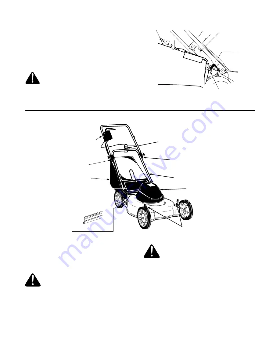
Place the hooks of the grass catcher into the slots
in the handle bracket assembly on each side of the
lower handle as shown in Figure 8. Release the
rear discharge door.
To remove the grass catcher, lift the rear discharge
door on the mower. Lift the grass catcher up, out of the
slots in the handle bracket assemblies. Release the
rear discharge door.
WARNING: Do not operate this mower with
the chute door open, unless the complete
grass catcher is properly mounted on the
mower.
Figure 8
SECTION 5: KNOW YOUR LAWN MOWER
Figure 9
Read this operator’s manual and safety rules before
operating your lawn mower. Compare the illustration in
Figure 9 with your lawn mower to familiarize yourself
with the location of various controls and adjustments.
Save this manual for future reference.
WARNING: The operation of any lawn
mower can result in foreign objects being
thrown into the eyes, which can damage
your eyes severely. Always wear safety
glasses while operating the mower, or
while performing any adjustments or
repairs.
Motor/Blade Control Assembly
The motor/blade control is located on the upper handle
of the mower. See Figure 9. The motor/blade control
handle engages and disengages the motor and blade.
WARNING:
The motor/blade control assembly
is a safety device. Never attempt to bypass its
operations.
Rear Trailing Shield
The rear trailing shield, attached between the rear
wheels of your mower, is provided to minimize the
possibility of objects being thrown at the operator from
the rear of the mower. See Figure 9.
Circuit Breaker
The mower is equipped with a circuit breaker, located
on the motor/blade control. Refer to Figure 10. This
circuit breaker may trip when too much strain is placed
on the mower. See
Making Adjustments Section
.
Rear Discharge Door
Hook
Slot On
Handle
Bracket
Grass Catcher Bag
Handle Insulator
Handle Insulator
Lower Handle
Cord Restraint
Motor/Blade Control Assembly
Electric Motor
Grass Catcher
Rear Discharge Door
Height Adjustment Lever
Rear Trailing Shield


