background image

ULTRA ELITE FACEPIECE

REMOVING THE COMPONENT HOUSING ASSEMBLY

Note:

Remove the adapter assembly and the component

housing cover.

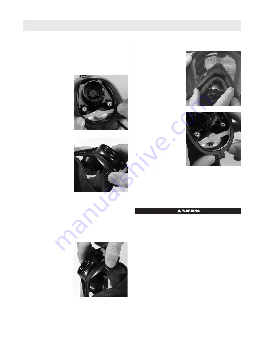
1. Use a small phillips screwdriver to remove the compo-

nent housing ring screw.

2. Grasp the ring with the

thumb and forefinger of
each hand. Gently
spread the ring halves
apart at the bottom.

3. When the facepiece

rubber is out of the ring
groove, lift the ring up
away from the face-
piece. You may need to
pull the housing down
slightly to allow enough
room to remove the
ring from between the
housing and the lower
lens ring.

4. Remove the facepiece rubber from the component

housing and pull the housing and nosecup (if installed)
out of the facepiece.

INSTALLING THE COMPONENT HOUSING ASSEMBLY

1. Slide the housing into the front of the facepiece.

2. Starting at the top

(narrow end) of the
housing, place the
housing in the face-
piece groove. Work the
rubber all the way
around the housing.
Check that the housing
is completely captured
inside the groove and
the center-lines are
lined up.

3. Moisten the facepiece housing area and the inside of

the housing ring.

4. Insert the narrow end of the ring into the space

between the lower lens ring and the facepiece housing
area.

5. Line up the component

housing ring mark with
the facepiece center-
line.

6. Starting at the top,

work the housing ring
down on the facepiece
to capture the face-
piece rubber in the ring
groove. Work your way
down each side of the
ring until the facepiece
rubber is completely
captured inside the
ring.

7. Gently squeeze the ring halves together at the bottom

of the housing. Watch the facepiece rubber at the top
as you do this. If you see any bulges or wrinkles in the
facepiece rubber, it is not captured in the groove.
Rework the ring around the facepiece rubber until
there are no bulges or wrinkles.

Bulges or wrinkles mean that the facepiece rubber is
not seated correctly in the ring. Re-install the ring to
seat it correctly. Failure to follow this warning can
cause the facepiece to leak and result in serious per-
sonal injury or death.

8. When the housing ring appears to be seated, grasp

the outside of the ring and the inside of the housing at
the top between your thumb and forefinger and
squeeze them together. Then do the same with the
ring halves at the bottom.

9

TAL 805 (L) Rev. 4 - 10042830

Summary of Contents for FireHawk Ultra Elite 10048813

Page 1: ...Ultra Elite Facepiece TAL 805 L Rev 4 MSA 2008 Prnt Spec 10000005389 I Mat 10042830 Doc 10000015248 MAINTENANCE AND REPAIR...

Page 2: ...811 Component Housing Ring 14 804812 Screw Kit 15 10018621 Slide Adapter Ass y 15a 10033115 Push To Connect Adapter Ass y 15b 813556 1 4 Turn Adapter Ass y 17 804829 Neckstrap 18 815604 Component Hous...

Page 3: ...10042830 ULTRA ELITE FACEPIECE 7a 7 7b 15b 23 24 3 12 27 in lbs pressure demand facepiece NFPA Facepiece Components Type Small Medium Large Hycar 10048814 10048813 10048815 Silicone 805581 805580 8055...

Page 4: ...4 TAL 805 L Rev 4 10042830...

Page 5: ...operly Note Do not force dry the parts by placing them in a heater or in direct sunlight The rubber will deteriorate When the facepiece is thoroughly dry store the facepiece in the plastic bag that it...

Page 6: ...ng freeing retainer from slots in the housing Lift the retainer and the spring out of the component hous ing Discard spring and spring retainer Be careful not to damage the slots or valve seat in the...

Page 7: ...he octagon flange on the adapter b Thread the adapter assembly into the facepiece Use the spanner wrench to torque the adapter to 12 27 in lbs If necessary continue to torque until the top flat on the...

Page 8: ...the groove Work the face piece rubber flange around the lens to fully seat the lens in the groove When installed correctly the bottom lens center line mark lines up with the bottom face piece center...

Page 9: ...ea and the inside of the housing ring 4 Insert the narrow end of the ring into the space between the lower lens ring and the facepiece housing area 5 Line up the component housing ring mark with the f...

Page 10: ...2 Remove the disc from the gasket and inspect both for wear The disc should be very soft and pliable Install a new disc valve if it is damaged or hardened 3 To install the inhalation disc valve a Gen...

Page 11: ...Housing Cover and Adapter 1 Gently stretch the hole in the center of the inlet disc valve over and onto the gasket stem 2 With the pull tab facing outward insert the gasket into the facepiece at an an...

Page 12: ...ontinue to tighten until the top flat of the adapter octagon is horizontal Note The octagon flats on the facepiece adapter must align with octagon flats of component housing d Press in on the front of...

Page 13: ...pter through the facepiece component housing cover Thread the adapter assembly into the facepiece 3 Tighten facepiece adapter until the top flat on the octagon is horizontal Note The octagon flats on...

Page 14: ......

Reviews: