LambdaDriver 400 & 800
ML46430, Rev. 07
October 2004
LASER EN: Normal operation mode of TM-DXFP
Transponder. In this mode, the Transponder
transmits in the access and WDM directions
irrespective of whether it receives.
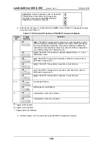
, locate DIP switch
SW1
on the TM-DXFP Transponder module.
and set it using
Table 15: DIP Switch SW1 Setting of TM-DXFP Transponder Module
Toggle
No.
Toggle
Position
Function
RED: TM-DXFP Transponder to operate in mutual redundancy mode
with its companion transponder model in the
same
LDx00 and having
the same operating wavelength. (This jumper setting is sufficient for
redundancy mode operation; there is no need for further configuration,
e.g., software using CLI commands, etc.)
1
NOR: TM-DXFP Transponder to operate independently, i.e., in non-
redundancy mode.
RLB: TM-DXFP Transponder to operate in RLB test mode, which is
described in Appendix C.
2
NOR: TM-DXFP Transponder to operate in normal mode.
LLB: TM-DXFP Transponder to operate in LLB test mode, which is
described in Appendix C.
3
NOR: TM-DXFP Transponder to operate in normal mode.
10.3 Gbps Ethernet
4, 5
9.95 Gbps OC-192/STM-64
Configuration control by software.
6
Configuration control by hardware.
Toggle in ON position.
Toggle in OFF position.
Toggle position immaterial.
3. Perform Steps 1 to 2 for each and every TM-DXFP Transponder module.
110


