Page 19
mrcool.com
Unit Installation
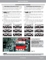
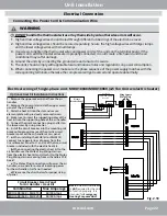
Connecting the Power Cord & Communication Wire
WARNING
1.
Before work begins, please check to ensure the unit and thermostat are powered “
OFF
”.
2.
Match the terminal numbers and wire colors with the colors indicated in the indoor unit.
3.
Incorrect wiring connections could burn the electrical components.
4.
Connect the wires securely to the wiring box. Incomplete installation could lead to a fire hazard.
5.
Please use wire clamps to secure the external covers of connecting wires. (Insulators must be
clamped securely; otherwise, electrical leakage may occur.)
6.
Ground wire should be securely connected.
Power
Indoor unit
AP1
G
L1
L2
Fan motor
X1
1
XT3
DC_MOTOR1
TC
RD
BU
BK
YE
WH
1
X1
2 3 4 5 6
G
M
XT1- L1
XT1- L2
8KW HEAT KIT
G
CB1
CB1
L1
L2
G
YEGN
W1 W2
BK
RD
AP2
G
CN1
COM2
W 7 W8
W9
W10
W11
W5
W4
W12
Code
Name
CB1
Circuit breaker
TC
Transformer
XT1~XT3
Wiring board
Y
B
4-way valve control
signal, energized under
the heating mode
W1
Heater control signal
R
24V AC power supply
C
24V common
G
Indoor unit fan signal
Heat
W13
X1 X2
X10
X4
X3
X9
X13 X7
L1
L2
XT1
L1
L1
L1
L2
L2
L2
Y
B
W1
R
C
G
Y
XT2
C
Y
G G
Y
C
B
B
B
W1
W1 W1
R
R
R
C
①
_
Note:
1.Please refer to the instruction manual to check whether the unit can connect to the engineering electric heating.
2.When the unit doesn’t connect to the engineering electric heating, connect the engineering power supply to the L1 and L2 of wiring board.
3.When the unit connects to the engineering electric heating, connect the engineering power supply to the breaker.
4.The primary input voltage of transformer is defaulted at 230V(BK). When switching the power supply of the complete unit to 208V, connect the primary input voltage of transformer to 208V(BU),
which can be realized by exchanging the black wire and the blue wire.
①
5.
①
Only applicable for units with ground wire.
Thermostat
X1
G
CB1 CB2
CB2 CB1
L1
L2
G
15KW HEAT KI T
HEAT
Electrical Connection
Fig 2.13

