NOTE
Refer to the Universal Condenser Manual for the Dip Switch instructions and settings for the condenser.
mrcool.com
Page 16
HEAT (SA2) COOL (SA1)
HEAT (SA2)
COOL (SA1)
HEAT (SA2)
COOL (SA1)
4 Ton Settings
5 Ton Settings
Medium Fan Settings
High Fan Settings
Low Fan Settings
HEAT (SA2) COOL (SA1)
HEAT (SA2)
COOL (SA1)
HEAT (SA2)
COOL (SA1)
Medium Fan Settings
High Fan Settings
Low Fan Settings
Unit Installation
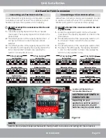
Converting a 3-Ton Unit to 2-Ton
Follow these instructions during unit installation in order
to enable a Universal
®
Series 3-ton condenser and air
handler split system to operate at 2-ton capacity.
DO NOT
attempt this conversion while the unit
is powered on.
1.
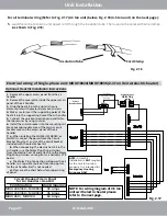
Locate the capacity dip switch on the air handler
main board. The capacity dip switch is circled on the
photo below.
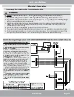
2.
The default position of the capacity dip switch is 1, 2,
& 4 ‘Up’ and 3 ‘Down’ on both the SA2 and SA1
switches.
3.
The default position of the capacity dip switch is 36K.
4.
To activate the 24K capacity, flip capacity dip switch 2
& 4 on SA2 and SA1 to Down. Flip capacity dip
switch 3 on SA2 and SA1 to Up.
Air Handler Field Conversion
Follow these instructions during unit installation in order
to enable a Universal
®
Series 5-ton condenser and air
handler split system to operate at 4-ton capacity.
DO NOT
attempt this conversion while the unit
is powered on.
1.
Locate the capacity dip switch on the air handler
main board. The capacity dip switch is circled on the
photo below.
2.
The default position of the capacity dip switch is 2, 3,
& 4 ‘Up’ and 1 ‘Down’ on both the SA2 and SA1
switches.
3.
The default position of the capacity dip switch is 60K.
4.
To activate the 48K capacity, flip capacity dip switch
1, 3, & 4 on SA2 and SA1 to Down. Flip capacity dip
switch 2 on SA2 and SA1 to Up.
HEAT (SA2)
COOL (SA1)
HEAT (SA2)
COOL (SA1)
HEAT (SA2)
COOL (SA1)
2 Ton Settings
HEAT (SA2)
COOL (SA1)
HEAT (SA2)
COOL (SA1)
HEAT (SA2)
COOL (SA1)
3 Ton Settings
Medium Fan Settings
High Fan Settings
Medium Fan Settings
High Fan Settings
Low Fan Settings
Low Fan Settings
Converting a 5-Ton Unit to 4-Ton
Location of Dip Switch on
Air Handler Main Board
This is an example for switch
location only. Refer to the
illustrations above for settings.
NOTE ON DIP SWITCH
ORIENTATION
Depending on your
application, and the position
unit is mounted in, the DIP
Switches may be upside down.
Fig 2.12

