background image

DCA-70SSJU SERIES — OPERATION AND PARTS MANUAL (STD)— REV. #5  (06/03/03) — PAGE 87

1

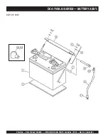
DCA-70SSJU SERIES — BATTERY ASSY.

BATTERY ASSY.

NO.

PART NO.

PART NAME

QTY.

REMARKS

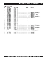
1

551010280

BATTERY ................................................... 1 ............... 627MFD

..................................................................................... REPLACES 0602220187

2

M9310500014

BATTERY SHEET

1

3

M9103000304

BATTERY BAND

1

4

0602220920

BATTERY BOLT SET

2

5

0040006000

LOCK WASHER

2

6

M1346400004

BATTERY CABLE ....................................... 1 ............... S/N7300001 TO S/N7302045

6

M1346400204

BATTERY CABLE ....................................... 1 ............... S/N7302046~

7

M2346400104

BATTERY CABLE

1

8

011008020

HEX HEAD BOLT ....................................... 1 ............... REPLACES 0016908020

0040508000

TOOTHED WASHER

1

9

CABLE, GROJND ...................................... 1 ............... MAKE LOCALLY

10

0017112025

HEX HEAD BOLT

1

10

0040512000

TOOTHED WASHER

1

11

012210020

HEX HEAD BOLT ....................................... 1 ............... REPLACES 0017110020

11

0040510000

TOOTHED WASHER

1

12

M1346400004

TERMINAL COVER ................................... 1 ............... S/N7300001 TO S/N7300003

..................................................................................... REPLACES M9310000304

13

M1346400104

TERMINAL COVER ................................... 1 ............... S/N7300001 TO S/N7300003

..................................................................................... REPLACES M9310000204

Summary of Contents for WHISPERWATT DCA-70SSJU

Page 1: ... 310 537 3700 SERVICE DEPARTMENT 800 421 1244 800 835 2551 FAX 310 537 3927 FAX 310 638 8046 E mail mq multiquip com www multiquip com OPERATION AND PARTS MANUAL MQ POWER DCA 70SSJU WHISPERWATTTM GENERATOR S N 7300000 2140 KEY START S N 7302141 3869 ECU EGS PARTS LIST NO M1870300034A Revision 5 06 03 03 COPYRIGHT 2003 MULTIQUIP INC ...

Page 2: ...PAGE 2 DCA 70SSJU SERIES OPERATION AND PARTS MANUAL STD REV 5 06 03 03 ...

Page 3: ...ASE HAVE THE MODEL AND SERIAL NUMBER ON HANDWHEN CALLING PARTS DEPARTMENT 800 427 1244 or 310 537 3700 FAX 800 672 7877 or 310 637 3284 SERVICE DEPARTMENT 800 421 1244 FAX 310 537 4259 TECHNICAL ASSISTANCE 800 478 1244 FAX 310 631 5032 WARRANTY DEPARTMENT 888 661 4279 or 310 661 4279 FAX 310 537 1173 ...

Page 4: ...ering Procedures 5 Specifications 6 Dimensions Top Side Front 7 Safety Message Alert Symbols 8 9 Rules for Safe Operation 10 13 Installation 14 15 Towing Safety Precaution 16 Trailer Specifications 17 19 Generator Decals 20 21 General Information 22 Major Components 23 Generator Control Panel 24 Engine Operating Panel up to S N 73002140 25 Engine Operating Panel S N 73002140 26 27 OutputTerminal P...

Page 5: ...0 Ext 279 Multiquip s Main Phone Numbers 800 421 1244 Fax 310 537 3927 310 537 3700 Note Unlessotherwiseindicatedbycustomer all orders are treated as Standard Orders and will ship within 24 hours We will make every effort to ship AirShipments thesamedaythattheorderis received ifpriorto2PMwestcoasttime Stock Orders must be so noted on fax or web forms Extra Discounts All parts orders which include ...

Page 6: ... P C A x u A z H 0 6 e s a h P e l g n i S e g a t l o V V 0 2 1 t u p t u O 2 x W K 4 2 W K 8 4 s n o i t a c i f i c e p S e n i g n E l e d o M 0 5 1 F T 5 4 0 4 E R E E D N H O J e p y T d e g r a h c o b r u t n o i t c e j n i t c e r i d d e l o o c r e t a w e l c y C 4 s r e d n i l y C f o o N s r e d n i l y c 4 e k o r t S x e r o B m m 7 2 1 x m m 6 0 1 n i 5 x n i 9 1 4 t u p t u O d...

Page 7: ...DCA 70SSJU SERIES OPERATION AND PARTS MANUAL STD REV 5 06 03 03 PAGE 7 1 DCA 70SSJU SERIES DIMENSIONS TOP SIDE AND FRONT Figure 1 Dimensions ...

Page 8: ...gases contain poisonous carbon monoxide This gas is colorless and odorless and can cause death if inhaled NEVER operate this equipment in a confined area or enclosed structure that does not provide ample free flow air Potential hazards associated with trowel operation will be referenced with Hazard Symbols which appear throughout this manual and will be referenced in conjunction with Safety Messag...

Page 9: ...nt can result if operating in speed ranges above maximum allowable Respiratory Hazard ALWAYS wear approved respiratory protection ALWAYS wear approved eye and hearing protection Sight and Hearing hazard Equipment Damage Messages Other important messages are provided throughout this manual to help prevent damage to your trowel other property or the surrounding environment This generator other prope...

Page 10: ...xplosion or fire could result causing severe bodily harm or even death High Temperatures Allow the engine to cool before performing service and maintenance functions Contact with hot components can cause serious burns The engine of this generator requires an adequate free flow of cooling air NEVER operate the generator in any enclosed or narrowareawherefree flow of the air is restricted If the air...

Page 11: ...the machine and place the circuit breaker in the OFF positionwhencontact with the output terminals is required There exists the possibility of electrocution electrical shock or burn which can cause severe bodily harm or even death Never use damaged or worn cables when connecting equipment to the generator Makesurepower c o n n e c t i n g cables are securely connected to the generator s output ter...

Page 12: ...y is not charged a buildup of combustible gas will occur 4 ALWAYSkeepbatterychargingandcablesingoodworking condition Repair or replace all worn cables 5 ALWAYS recharge the battery in an vented air environment to avoid risk of a dangerous concentration of combustible gases 6 In case the battery liquid dilute sulfuric acid comes in contact with clothing or skin rinse skin or clothing immediately wi...

Page 13: ... Trailer tires should be inflated to 50 psi cold Also check the tire tread wear on both vehicles ALWAYS make sure the trailer is equipped with a Safety Chain ALWAYS attach trailer s safety chains to towing vehicle properly ALWAYS make sure the vehicle and trailer directional backup brake and trailer lights are connected and working properly The maximum speed for highway towing is 45 MPH unless pos...

Page 14: ...PAGE 14 DCA 70SSJU SERIES OPERATION AND PARTS MANUAL STD REV 5 06 03 03 Figure 2 Typical Generator Grounding Application DCA 70SSJU INSTALLATION ...

Page 15: ...cause the engine to heat excessively and possibly burn the valves Mounting The generator must be mounted on a solid foundation such as concrete and set firmly on the foundation to isolate vibration of the generator when it is running The generator must set at least 6 inches above the floor or grade level in accordance to NFPA 110 Chapter 5 4 1 DO NOT remove the metal skids on the bottom of the gen...

Page 16: ...ailer Also check the tire tread wear on both vehicles ALWAYS make sure the trailer is equipped with a Safety Chain DCA 70SSJU SERIES TOWING SAFETY PRECAUTIONS ALWAYS attach trailer s safety chain to bumper of towing vehicle ALWAYS make sure the vehicle and trailer directional backup brake and trailer lights are connected and working properly The maximum speed for highway towing is 55 MPH unlesspos...

Page 17: ...condition Check the tires for proper inflation and wear Also check the wheel lug nuts for proper tightness 5 Frame Length Measurement is from fender to fender 6 Jack Stand Trailer support device with maximum pound requirement from the tongue of the trailer 7 Coupler Type of hitch used on the trailer for towing 8 Tire Size Indicates the diameter of the tire in inches 10 12 14 etc and the width in m...

Page 18: ... L 0 0 8 L E E H W T L I T L L U F W 0 7 R L R T 0 6 5 4 A C D 0 7 O N E G R U S S B L 0 0 0 7 6 8 1 7 7 B L 0 0 0 2 D A P T A L F X 0 7 R L R T 0 6 5 4 A C D 0 7 T P O E G R U S S B L 0 0 0 7 8 3 1 6 6 B L 0 0 0 2 D A P T A L F F X 0 7 R L R T 0 6 5 4 A C D 0 7 L A G 3 5 E G R U S S B L 0 0 0 7 8 3 1 6 6 B L 0 0 0 2 D A P T A L F F X 0 0 1 R L R T 5 2 1 0 0 1 A C D L A G 0 5 1 C I L U A R D Y H E...

Page 19: ... 4 1 s b l 0 0 5 3 3 G U L 5 F A E L 5 E L O P 4 T A L F R E B B U R X 0 7 R L R T S S A L C L L A B 2 E L B A T S U J D A 3 C 4 1 5 0 2 4 S A I B 5 X 4 1 s b l 0 0 5 3 3 G U L 5 F A E L 5 E L O P 4 T A L F R E B B U R F X 0 7 R L R T S S A L C L L A B 2 E L B A T S U J D A 3 C 4 1 5 0 2 4 S A I B 5 X 4 1 s b l 0 0 5 3 3 G U L 5 F A E L 5 E L O P 4 T A L F R E B B U R F X 0 0 1 R L R T 2 E L B A T...

Page 20: ... a number of safety decals These decals are provided for operator safety and maintenance information The illustration below and on the preceding page show the decals as they appear on the machine Should any of these decals become unreadable replacements can be obtained from your dealer DCA 70SSJU SERIES GENERATOR DECALS ...

Page 21: ...DCA 70SSJU SERIES OPERATION AND PARTS MANUAL STD REV 5 06 03 03 PAGE 21 1 DCA 70SSJU SERIES GENERATOR DECALS ...

Page 22: ...elta A B C and D Duringsteadystateloads thepowerfromthevoltageregulator is supplied from the parallel connections of A to B A to D and C to D These three phases of the voltage input to the voltage regulatorarethenrectifiedandaretheexcitationcurrentforthe exciter section When a heavy load such as a motor starting or a short circuit occurs the automatic voltage regulator AVR switches the configurati...

Page 23: ...O N M E T I N O I T P I R C S E D 1 y l b m e s s A r e l f f u M 2 y l b m e s s A e n i g n E 3 y l b m e s s A e r u s o l c n E 4 y l b m e s s A r o t a r e n e G 5 y l b m e s s A l a n i m r e T t u p t u O 6 y l b m e s s A k n a T l e u F 7 y l b m e s s A y r e t t a B 8 y l b m e s s A l e n a P l o r t n o C r o t a r e n e G 9 y l b m e s s A l e n a P g n i t a r e p O e n i g n E ...

Page 24: ...two phases of the output terminals or to be switched off 5 Voltage Regulator Control Allows 15 manual adjustment of the generator s output voltage 6 Frequency Meter Indicates the output frequency in hertz Hz Normally 60 Hz 1 Hz 7 AC Voltmeter Indicates the output voltage present at the UVWO terminals Located behind the generator control panel is the Generator Control Box This box contains some of ...

Page 25: ...ter Gauge Indicates the current being supplied by the engine s alternator which provides current for generator s control circuits and battery charging system 6 Fuel Gauge Indicates amount of diesel fuel available 7 Tachometer Indicates engine speed in RPM s for 60 Hz operation This meter should indicate 1800 RPM s when the rated load is applied In addition a built in hour meter will record the num...

Page 26: ...PAGE 26 DCA 70SSJU SERIES OPERATION AND PARTS MANUAL STD REV 5 06 03 03 Figure 7 Engine Operating Panel From S N 73002141 DCA 70SSJU SERIES ENGINE OPERATING PANEL ...

Page 27: ...l major faults will shutdown the generator A Off Manual Auto Switch This switch controls the running of the generator If this switch is left in the OFF position the generator will not run When this switch is set to the manual position the generator will start immediately If the generator is to be connected to a building s AC power source via a transfer switch isolation place the switch in the auto...

Page 28: ...ptacles 20 amp Two 2 GFCI Circuit Breakers 120V 20 amps One Main Circuit Breaker 250V 175 amps Five 5 Output Terminal Lugs Output Terminal Panel TheOutputTerminalPanel Figure8 shownbelowislocated ontheright handside leftfromcontrolpanel ofthegenerator Lift up on the cover to gain access to receptacles and terminal lugs NOTE Terminal legs O and Ground are considered bonded grounds Figure 8 Output T...

Page 29: ...minals Turn the voltage regulator control knob Figure 11 on the control panel to obtain the desired voltage Turning the knob clockwise will increasethe voltage turning the knob counter clockwise will decrease the voltage Figure 10 240 VAC Twist Lock Auxiliary Receptacles DCA 70SSJU SERIES OUTPUT TERMINAL PANEL FAMILIARIZATION Twist Lock DualVoltage 120 240VAC Receptacles There are three 240 VAC 50...

Page 30: ...rload a 3 pole 175 amp main circuit breaker is provided Make sure to switch ALL circuit breakers to the OFF position prior to starting the engine DCA 70SSJU SERIES OUTPUT TERMINAL PANEL FAMILIARIZATION Over Current Relay An over current relay Figure 14 is connected to the main circuit breaker In the event of an overload both the circuit breaker and the over current relay may trip If the circuit br...

Page 31: ...ng set s rated output kW can be used When connecting a fluorescent or mercury lamp a capacity of up to the generating set s rated output kW multiplied by 0 6 can be used When connecting an electric drill or other power tools pay close attention to the required starting current capacity NOTE WATTS VOLTAGE x AMPERAGE Three Phase Load When calculating the power requirements for 3 phase power use the ...

Page 32: ... load from being switched while the engine is running To lock the voltage selector switch press and hold the red button located at the bottom of the switch Figure 15 Voltage Selector Switch DCA 70SSJU SERIES GENERATOR OUTPUTS Generator Amperage Tables 7 and 8 describe the generator s current output capa bility for both 1Ø phase and 3Ø phase applications e l b a l i a v A s e g a t l o V 6 e l b a ...

Page 33: ...ut on the selected leg Figure 16 Voltage Selector Switch 240 139V Three Phase Position for 3Ø 208V 120V voltage Figure 17 AC Voltmeter Change Over Switch Figure 18 AC Voltmeter Gauge Volt reading on W U Lug Use this position for 3Ø 208V 1Ø 120V A 0 40 60 75 20 Figure 20 AC Ammeter Amp reading on U lug Figure 19 AC Ammeter Change Over Switch The ammeter and voltmeter gauges areonlyactivewhenthe UVW...

Page 34: ... Lugs 240 139V Three Phase Connections 2 Connect the load wires to the UVWO terminals as shown in Figure 22 3 Turn the voltage regulator knob Figure 23 clockwise to increase voltage output turn counterclockwise to decrease voltage output 3Ø 208V 1Ø120V UVWOTerminal OutputVoltages 1 Place the voltage selector switch in the 3Ø 240 139 position as shown in Figure 24 Figure 23 Voltage Regulator Knob 1...

Page 35: ...crease voltage output turn counterclockwise to decrease voltage output 1Ø 240V 120V UVWOTerminal OutputVoltages 1 Place the voltage selector switch in the 1Ø 240 120 position as shown in Figure 30 Figure 29 Voltage Regulator Knob 139V 240V 2 Connect the load wires to the UVWO terminals as shown in Figure 31 3 Turn the voltage regulator knob Figure 32 clockwise to increase voltage output turn count...

Page 36: ... WARNING WARNING WARNING WARNING WARNING ONLY properly trained personel who have read and understand this section should refill the double fuel tank system Use 2 diesel fuel Figure 34 Double Fuel Tank System Fuel spillage on a hot engine can cause a fire or explosion If fuel spillage occurs wipe up the spilled fuel completely to prevent fire hazards NEVER smoke around or near the generator DANGER ...

Page 37: ... trailer fuel tank Figure 37 first Figure 37 Fuel Tank Filling Order CAUTION CAUTION CAUTION CAUTION CAUTION DANGER DANGER DANGER DANGER DANGER WARNING WARNING WARNING WARNING WARNING Figure 36 Only Fill on Level Ground ONLY use 2 diesel fuel when refueling Diesel fuel and its vapors are dangerous to your health and the surrounding environment Avoid skin contact and or inhaling fumes ALWAYS fill t...

Page 38: ...r fuel expansion Fuel expands when heated 4 Once the trailer tank is full the secondary inner tank can be filled See Figure 39 Notice how the trailer filler tube level rises when the internal tank is filled 5 Figure 40 below reflects a full fuel system 6 Fuelfromtheenginereturnlinewilldrainintothesecondary internal fuel tank This fuel will eventually drain into the primary trailer tank in order to...

Page 39: ...ON CAUTION CAUTION CAUTION Cleaning the Radiator The engine may overheat if the radiator fins become overloaded with dust or debris Periodically clean the radiator fins with compressed air Cleaning inside the machine is dangerous so clean only with the engine turned off and the negative battery terminal disconnected Air Cleaner Periodic cleaning replacement is necessary Inspect it in accordance wi...

Page 40: ...or connections are exposed insulation missing replace wiring immediately Piping and Hose Connection Inspect all piping oil hose and fuel hose connections for wear and tightness Tighten all hose clamps and check hoses for leaks If any hose fuel or oil lines are defective replace them immediately If the battery cable is connected incorrectly electricaldamagetothe generator will occur Pay close atten...

Page 41: ...O terminals are protected by a plastic cover remove this cover to gain access to the terminals Tighten terminal nuts securely to prevent load wires from slipping out 1 Placethemain G F C I andaux circuitbreakers Figure45 in the OFF position prior to starting the engine 2 Connect the load to the UVWO terminals or auxiliary receptacles as shown in Figure 46 These load connection points can be found ...

Page 42: ...tion Switch Start 9 Turn the ignition key to the START position Figure 52 and listen for the engine to begin cranking After the engine starts release the ignition key Figure 51 Engine Throttle Control 10 Once the engine has started let it run for 3 5 minutes then turn the throttle handle control Figure 53 to the HIGH position 6 Press and hold the engine cold starting button Figure 49 until the but...

Page 43: ...s the coolant temperature should be between 165 and 215 degrees Fahrenheit Green Zone Figure 59 Coolant Temperature Gauge Figure 61 Main Aux and GFCI Circuit Breakers ON 17 Place the main GFCI and aux circuit breakers in the ON position Figure 61 18 Observe the generator s ammeter Figure 62 and verify it reads the anticipated amount of current with respect to the load The ammeter will only display...

Page 44: ...tion CAUTION Before Starting EngineOperatingPanelS N73002141 Steps 20 thru 31 are referenced for Engine Operating Panel S N 73002141 Figure63 Thisunit does not have a key ignition switch or a throttle lever It does havean enginespeedswitch that is used in conjunction with the MPEC unit Figure 63 Engine Operating Panel S N 73002141 20 Perform steps 1 through 4 in the BeforeStarting section page 41 ...

Page 45: ...ber the generator can start up at any time without warning NEVER attempt to perform any maintenance when the generator is in the auto mode WARNING When connecting the generator to a isolation transfer switch ALWAYS have power applied to the generator s internal battery charger This will ensure that the engine will not fail due to a dead battery CAUTION Figure 70 Off Manual Auto Switch AUTO 30 Plac...

Page 46: ...igure 45 to the OFF position 2 Place the engine throttle control in the LOW position Figure 71 Figure 71 Engine Throttle Control Low 3 Let the engine cool by running it for 3 5 minutes with no loadapplied 4 Turn the Ignition Key Switch Figure 72 to the OFF position Figure 72 Engine Ignition Switch Stop 5 Remove all loads from the generator NEVER stop the engine suddenly except in an emergency DO N...

Page 47: ...aner with Dust Indicator This indicator is attached to the air cleaner When the air cleaner element is clogged air intake restriction becomes greater and the dust indicator signal shows RED meaning the element needs changing After changing the air element press the dust indicator button to reset the indicator E C N A N E T N I A M N O I T C E P S N I 4 1 E L B A T s r H 0 1 Y L I A D s r H 0 5 2 s...

Page 48: ...fter disassembling the fuel system bleed the system according to the following procedure To restart after running out of fuel turn the switch to the ON position for 15 30 seconds Try again if needed This unit is equipped with an automatic air bleeding system Cleaning the Fuel Strainer Clean the fuel strainer if it contains dust or water Remove dust or water in the strainer cap and wash it in gasol...

Page 49: ...es will ONLY function when commercial power has been supplied to them Figure 75 To apply commercial power to these receptacles a power cord of adequate size will be required SeeTable 5 When using the generator in hot climates there is no reason to apply power to jacket water heater However if the generator will be used in cold climates it is always a good idea to apply power to the jacket water he...

Page 50: ...aulicsurgebrakingrequirestheinstallationofanactuator at the tongue of the trailer Remember the surge or push of the trailer toward the tow vehicle automatically synchronizes the trailer brakes with the tow vehicle brakes As the trailer pushes against the tow vehicle the actuator telescopes together and applies force to the master cylinder supplying hydraulic pressure to the trailer brakes Periodic...

Page 51: ...he leaf suspension springs and associated components Figure 77 should be visually inspected every 6 000 miles for signs of excessive wear elongation of bolt holes and loosening of fasteners Replace all damaged parts suspension immediately Torqued suspension components as detailed in Table 17 Figure 77 Major Suspension Components DCA 70SSJU SERIES TRAILER MAINTENANCE WEAR PATTERN CAUSE SOLUTION Cen...

Page 52: ...g nuts all the way down Tighten each lug nut in 3 separate passes as defined byTable 18 3 After first road use retorque all lug nuts in sequence Check all wheel lug nuts periodically NEVER use an pneumatic air gun to tighten wheel lug nuts Figure 78 Wheel Lug Nuts Tightening Sequence DCA 70SSJU SERIES TRAILER MAINTENANCE s t n e m e r i u q e R e u q r o T e r i T 8 1 e l b a T e z i S l e e h W s...

Page 53: ...DCA 70SSJU SERIES OPERATION AND PARTS MANUAL STD REV 5 06 03 03 PAGE 53 1 DCA 70SSJU SERIES TRAILERWIRING DIAGRAM Figure 79 Trailer Towing Vehicle Wiring Diagram ...

Page 54: ...PAGE 54 DCA 70SSJU SERIES OPERATION AND PARTS MANUAL STD REV 5 06 03 03 DCA 70SSJU SERIES GENERATORWIRING DIAGRAM Figure 80 Generator Wiring Diagram ...

Page 55: ...DCA 70SSJU SERIES OPERATION AND PARTS MANUAL STD REV 5 06 03 03 PAGE 55 1 DCA 70SSJU SERIES ENGINEWIRING DIAGRAM WITH CONTROLLER Figure 81 Engine Wiring Diagram Controller ...

Page 56: ...PAGE 56 DCA 70SSJU SERIES OPERATION AND PARTS MANUAL STD REV 5 06 03 03 DCA 70SSJU SERIES ENGINE WIRING DIAGRAM WITH IGNITION SWITCH Figure 82 Engine Wiring Diagram with Ignition Switch ...

Page 57: ... n e r o l e u f d e i f i c e p s e h t e s U r e b m u n e n a t e c w o l h t i w l e u F l e u f d e i f i c e p s e h t e s U n o i t c e j n i e s o o l o t e u d k a e l l e u F t u n g n i n i a t e r e p i p t u n n e t h g i T g n i m i t n o i t c e j n i t c e r r o c n I t s u j d A n r o w t f a h s m a c l e u F e c a l p e R d e g g o l c e l z z o n n o i t c e j n I e l z z o n n...

Page 58: ...e l d e i f i c e p s e h t o t e c u d e R r o n r o w r e n i l d n a g n i r n o t s i P k c u t s e c a l p e r r o r i a p e R g n i m i t n o i t c e j n i t c e r r o c n I t s u j d A n o i s s e r p m o c t n e i c i f e D e c n a r a e l c p o t t s u j d A y a r g k r a d r o k c a l b r e h t i E d e v r e s b o s i s a g t s u a h x e d a o l r e v O d a o l e h t n e s s e L d e s u ...

Page 59: ...f e d R V A s I y r a s s e c e n f i e c a l p e R r e i f i t c e R g n i t a t o R e v i t c e f e D e c a l p e r d n a k c e h C t u p t u O e g a t l o V w o L t c e r r o c d e e p s e n i g n e s I h g i H o t r e v e l e l t t o r h t e n i g n e n r u T e s o o l s n o i t c e n n o c g n i r i w s I r i a p e r d n a g n i r i w k c e h C R V A e v i t c e f e D y r a s s e c e n f i e ...

Page 60: ... t r e p m e t t c e r r o c n i n o i s n e t t l e b n a F t l e b n a f e c a l p e r n e t h g i T r o t a i d a r h g u o r h t n o i t a l u c r i c t o n s i w o l f r i A l l i r g r o t a i d a r r i a p e r n a e l C n e p o s r o o D s r o o d e s o l C g n i k a e l t s u a h x E t r a p y t l u a f r o s t e k s a g r i a p e r e c a l p e R d e d a o l r e v o g n i e b r o t a r e n...

Page 61: ...DCA 70SSJU SERIES OPERATION AND PARTS MANUAL STD REV 5 06 03 03 PAGE 61 1 NOTE PAGE ...

Page 62: ...where a particular part is used Model Number Where indicated this shows that the correspondingpartisutilizedonlywiththisspecificmodelnumber or model number variant Items Found In the Items Number Column All parts with same symbol in the number column or belong to the same assembly or kit If more than one of the same reference number is listed the last one listed indicates newest or latest part ava...

Page 63: ...0001TO S N7300267 1 M2310500503 RADIATORHOSE UPPER S N7300268 1 M2310500603 RADIATOR HOSE LOWER S N7300268 1 0602100056 STARTER SWITCH S N7300001TO S N73002140 1 AR51481 KEY STARTER SWITCH S N7300001TO S N73002140 1 06021030912 LAMP PILOTALARM 1 0601810245 BULB PILOTLAMP 1 0602123263 WATERTEMPERATUREUNIT 1 0602122272 OIL PRESSURE UNIT 1 0605505070 FUELTANK CAP 5 0602042420 FUELTANK IN LINE FILTER ...

Page 64: ...PAGE 64 DCA 70SSJU SERIES OPERATION AND PARTS MANUAL STD REV 5 06 03 03 DCA 70SSJU SERIES NAMEPLATE AND DECALS NAMEPLATE AND DECALS ...

Page 65: ...WARNING 1 M90320000 17 M9510100004 DECAL CAUTION 1 M91010000 18 M9520100503 DECAL WARNING M91010010 1 REPLACES M9510100104 19 M9520100503 DECAL WARNING M91010020 1 REPLACES M9510100204 20 M9510200002 DECAL MQ 1 M91020000 21 M9520000004 DECAL GROUND 1 M92000000 22 M9520000104 DECAL AMMETER CHNG OVR SW 1 M92000010 23 M9520000204 DECAL VOLTMETERCHNG OVRSW 1 M92000020 24 M9520100004 DECAL WARNING 2 M9...

Page 66: ...PAGE 66 DCA 70SSJU SERIES OPERATION AND PARTS MANUAL STD REV 5 06 03 03 DCA 70SSJU SERIES GENERATOR ASSY GENERATOR ASSY ...

Page 67: ...0303 STATOR ASSY 1 22 0845041904 GROMMET 2 23 8101315202 END BRACKET 1 24 8101350013 FIELD ASSY EXCITER 1 25 0012110070 HEX HEAD BOLT 4 26 0042610000 LOCK WASHER 4 27 031110160 PLAIN WASHER 4 REPLACES 0041210000 28 0010110045 HEX HEAD BOLT 6 29 0040010000 LOCK WASHER 6 30 03111060 PLAIN WASHER 6 REPLACES 0041210000 31 8101310014 COVER BEARING 1 32 8131312014 GASKET BEARING 1 33 8101331003 COVER EN...

Page 68: ...PAGE 68 DCA 70SSJU SERIES OPERATION AND PARTS MANUAL STD REV 5 06 03 03 DCA 70SSJU SERIES CONTROL BOX ASSY CONTROL BOX ASSY ...

Page 69: ... N7300001TO S N7301040 13 0021304015 MACHINESCREW 2 REPLACES 0027104015 13 OEMAA8 HEX NUT 2 REPLACES 0207004000 14 0027104010 MACHINESCREW 2 S N7300001TO S N7301040 15 M2213500103 CONTROL BOX COVER 1 16 011106015 HEX HEAD BOLT 4 REPLACES 0016906015 17 M2923100004 SELECTOR SWITCH 1 VY 80 S 17A 47230107 KNOB SELECTOR SWITCH 1 18 M2213600203 SWITCH BRACKET 1 S N7300001TO S N7300003 18 M2213600213 SWI...

Page 70: ...PAGE 70 DCA 70SSJU SERIES OPERATION AND PARTS MANUAL STD REV 5 06 03 03 DCA 70SSJU SERIES CONTROL BOX ASSY CONT CONTROL BOX ASSY CONT ...

Page 71: ...5 1 S N7300001TO S N7300645 41 0027105015 MACHINESCREW 1 S N7300001TO S N7300645 42 0601826052 RELAY HH62S FDC12V 2 S N7300001TO S N7300645 43 0027103010 MACHINESCREW 4 S N7300001TO S N7300645 44 0602202592 STARTER RELAY AT141011 1 45 011106015 MACHINESCREW 2 REPLACES 0027106015 46 0601821370 RECTIFIER DE4503 1 REPLACES 0601823240 47 0027104020 MACHINESCREW 1 S N7300261 48 0602200478 EMERGENCY REL...

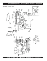
Page 72: ...PAGE 72 DCA 70SSJU SERIES OPERATION AND PARTS MANUAL STD REV 5 06 03 03 DCA 70SSJU SERIES ENGINE AND RADIATOR ASSY ENGINE AND RADIATOR ASSY ...

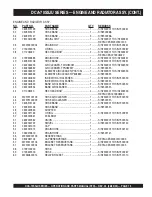
Page 73: ...5515148 HOSE BAND 1 S N7300001TO S N7300267 15 0602010780 FAN COVER 1 S N7300001TO S N7300267 16 0602060011 BLOWER FAN 1 320606 17 0602061000 FANSPACER 1 R81911 18 0012110090 FAN BOLT 19M7811 4 S N7300001TO S N7300220 REPLACES 0602060500 18 0012110095 HEX HEAD BOLT 4 S N7300401 19 011008015 HEX HEAD BOLT 6 S N7300001TO S N7300267 REPLACES 0013004308 20 0043004000 LOCKWASHER 4 S N7300001TO S N73002...

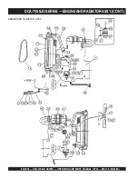
Page 74: ...PAGE 74 DCA 70SSJU SERIES OPERATION AND PARTS MANUAL STD REV 5 06 03 03 ENGINE AND RADIATOR ASSY DCA 70SSJU SERIES ENGINE AND RADIATOR ASSY CONT ...

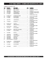
Page 75: ...TO S N7302330 42 0602040651 INDICATORAIRCLEANER 1 S N7302331 43 0602040590 BANDAIRCLEANER 2 S N7300001TO S N7302330 43 0602040554 BANDAIRCLEANER 1 S N7302331 44 011008020 HEX HEAD BOLT 4 S N7300001TO S N7302330 REPLACES 0016908020 46 M2373100103 HOSE AIR CLEANER 1 S N7300001TO S N7302330 46 M2375100003 HOSE AIR CLEANER 1 S N7302331 47 0605515146 HOSE BAND 2 S N7300001TO S N7302330 47 0605515146 HO...

Page 76: ...PAGE 76 DCA 70SSJU SERIES OPERATION AND PARTS MANUAL STD REV 5 06 03 03 DCA 70SSJU SERIES ENGINE AND RADIATOR ASSY CONT ENGINE AND RADIATOR ASSY ...

Page 77: ... REPLACES 0602122281 69 M9200100704 ADAPTER 1 S N7300646 70 1518183040 WATER SWITCH 1 S N 7300646 REPLACES 0602123282 71 M9200100404 ADAPTER 1 S N 7300646 72 012210020 HEX HEAD BOLT 1 S N7301311 REPLACES 0017110020 73 M2375200004 BRACKET AIR CLEANER 1 S N7302331 74 011008020 HEX HEAD BOLT 4 S N7302331 REPLACES 0016908020 75 020108060 HEX NUT 4 S N7302331 REPLACES 0207008000 76 0605515200 HOSE BAND...

Page 78: ...PAGE 78 DCA 70SSJU SERIES OPERATION AND PARTS MANUAL STD REV 5 06 03 03 DCA 70SSJU SERIES ENGINE OPERATING PANEL ASSY ENGINE OPERATING ASSY S N7300001TO S N7302140 S N73002141 ...

Page 79: ...10550 SNAPPIN 1 S N7300001TO S N7302140 10 M2354300104 GOVERNOR ROD 1 S N 730001TO S N7300003 10 M2354300114 GOVERNOR ROD 1 S N7300004TO S N7302140 11 0602180106 BALL JOINT 1 S N7300001TO S N7302140 12 020108060 HEX NUT 1 S N7300001TO S N7302140 REPLACES 0030008000 13 0602180107 BALL JOINT 1 S N7300001TO S N7302140 14 0039308000 HEX NUT 1 S N7300001TO S N7302140 REPLACES 0036508000 15 952404470 HE...

Page 80: ...PAGE 80 DCA 70SSJU SERIES OPERATION AND PARTS MANUAL STD REV 5 06 03 03 DCA 70SSJU SERIES ENGINE OPERATING PANEL ASSY CONT ENGINE OPERATING ASSY CONT S N7300001TO S N7302140 S N73002141 ...

Page 81: ...N7300645 21 0602123092 WATERTEMPERATURE GAUGE 100182 1 S N7300646 22 0602123263 UNIT WATERTEMPERATURE 0208900 1 S N7300001TO S N7300645 22 0602123261 UNIT WATERTEMPERATURE 0202500 1 S N7300646 23 0602121080 CHARGING AMMETER 1 100158 24 0602125090 FUEL GAUGE 1 100176 25 0602103092 ALARMLAMP 2 S N7300001TO S N7302140 25 0601810245 BULB 18V 2 S N7300001TO S N7302140 26 0601810141 PANEL LIGHT 1 27 060...

Page 82: ...PAGE 82 DCA 70SSJU SERIES OPERATION AND PARTS MANUAL STD REV 5 06 03 03 DCA 70SSJU SERIES OUTPUTTERMINAL ASSY S N7300061TO S N7302140 OUTPUT TERMINAL ASSY ...

Page 83: ...O S N7300365 11 0012108035 HEX HEAD BOLT 5 S N7300001TO S N7300365 REPLACES 0016908035 12 M2236100403 TERMINALCOVER 1 S N7300001TO S N7300060 12 M2236100413 TERMINALCOVER 1 S N7300061TO S N7301140 12 M2236100423 TERMINALCOVER 1 S N7301141TO S N7301260 12 M2236100433 TERMINALCOVER 1 S N7301261TO S N7302175 12 M2236100003 TERMINALCOVER 1 S N7302176 13 M2236100504 OUTPUT WINDOW 1 S N73012611TO S N730...

Page 84: ...PAGE 84 DCA 70SSJU SERIES OPERATION AND PARTS MANUAL STD REV 5 06 03 03 OUTPUT TERMINAL ASSY CONT DCA 70SSJU SERIES OUTPUTTERMINAL ASSY CONT ...

Page 85: ...V 50A 3 S N7300366 29 0021304015 MACHINESCREW 10 REPLACES 0027104015 29 0030004000 HEX NUT 10 REPLACES 0207004000 30 M2236100303 TERMINALCOVER 1 S N7300001TO S N7302175 30 M2455400003 TERMINALCOVER 1 S N7302176 31 012212045 HEX HEAD BOLT 2 REPLACES 0010112045 32 031112230 PLAINWASHER 2 REPLACES 0041212000 33 M9310200004 STAYRUBBER 2 34 0030012000 NUT 2 35 M2354200004 SUPPORTER GOVERNOR ROD 1 S N73...

Page 86: ...PAGE 86 DCA 70SSJU SERIES OPERATION AND PARTS MANUAL STD REV 5 06 03 03 DCA 70SSJU SERIES BATTERY ASSY BATTERY ASSY ...

Page 87: ...6 M1346400004 BATTERYCABLE 1 S N7300001TO S N7302045 6 M1346400204 BATTERYCABLE 1 S N7302046 7 M2346400104 BATTERYCABLE 1 8 011008020 HEX HEAD BOLT 1 REPLACES 0016908020 0040508000 TOOTHEDWASHER 1 9 CABLE GROJND 1 MAKELOCALLY 10 0017112025 HEX HEAD BOLT 1 10 0040512000 TOOTHEDWASHER 1 11 012210020 HEX HEAD BOLT 1 REPLACES 0017110020 11 0040510000 TOOTHEDWASHER 1 12 M1346400004 TERMINALCOVER 1 S N7...

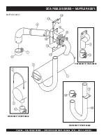
Page 88: ...PAGE 88 DCA 70SSJU SERIES OPERATION AND PARTS MANUAL STD REV 5 06 03 03 DCA 70SSJU SERIES MUFFLER ASSY S N7300001TO S N7300800 S N7300001TO S N7300800 S N7300001TO S N7300800 MUFFLER ASSY ...

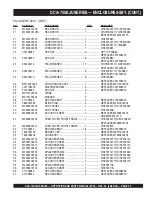
Page 89: ...5 M2333000223 EXHAUSTPIPE 1 S N7300181TO S N7300800 6 M2333300104 SEALCLAMP 1 S N7300001TO S N7300003 6 0602325065 CLAMP 1 S N7300004TO S N7300400 6 0602325066 CLAMP 1 S N7300401 7 011008040 HEX HEAD BOLT 2 S N7300001TO S N7300003 REPLACES 0010108040 8 M2333200004 GASKET 1 REPLACES M2333200014 9 0012108035 HEX HEAD BOLT 4 REPLACES 0016908035 10 M2333100204 TAILPIPE 1 S N7300001TO S N7300800 11 011...

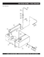
Page 90: ...PAGE 90 DCA 70SSJU SERIES OPERATION AND PARTS MANUAL STD REV 5 06 03 03 DCA 70SSJU SERIES FUELTANK ASSY FUEL TANK ASSY ...

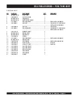
Page 91: ...7908000 6 0207308000 HEX NUT 2 S N7300611 6 031108160 PLAINWASHER 2 S N7300001TO S N7300610 REPLACES 0041208000 7 0222100178 RUBBERSHEET 4 8 M9200000003 DRAIN JOINT 1 9 M9200200004 DRAIN BOLT 1 10 0150000018 O RING 1 11 011206020 HEX HEAD BOLT 2 REPLACES 0016906020 12 M1363400104 DRAIN HOSE 1 13 0605515198 HOSE BAND 2 REPLACES 0605515198 14 0602042420 FUEL FILTER 1 PTG15P 15 0602042601 LEAK OFF LI...

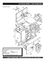
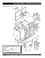
Page 92: ...CA 70SSJU SERIES ENCLOSURE ASSY ENCLOSURE ASSY ADD THE FOLLOWING DIGITS AFTER THE PART NUMBER WHEN ORDERING ANY PAINTED PANEL TO INDICATE COLOR OF UNIT 1 ORANGE 2 WHITE 3 SPECTRUM GRAY 4 SUNBELT GREEN 5 BLACK 6 CATERPILLARYELLOW 7 CATO GOLD THE SERIAL NUMBER MAY BE REQUIRED ...

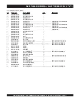
Page 93: ...7300003 8 M2423200313 INNER COVER FRONT FRAME 1 S N7300004 9 011008020 HEX HEAD BOLT 6 S N7300001TO S N7300003 REPLACES 0016908020 9 011008020 HEX HEAD BOLT 7 S N7300004 REPLACES 0016908020 10 M2433000203 CENTER FRAME 1 S N7300001TO S N7302175 10 M2435000203 CENTER FRAME 1 S N7302176 11 M2433000303 CENTER FRAME 1 12 0010114030 HEX HEAD BOLT 8 12 030214350 LOCKWASHER 8 REPLACES 0040014000 12 031114...

Page 94: ...SSJU SERIES ENCLOSURE ASSY CONT ENCLOSURE ASSY CONT ADD THE FOLLOWING DIGITS AFTER THE PART NUMBER WHEN ORDERING ANY PAINTED PANEL TO INDICATE COLOR OF UNIT 1 ORANGE 2 WHITE 3 SPECTRUM GRAY 4 SUNBELT GREEN 5 BLACK 6 CATERPILLARYELLOW 7 CATO GOLD THE SERIAL NUMBER MAY BE REQUIRED ...

Page 95: ...SHER 2 28 011008020 HEX HEAD BOLT 3 REPLACES 0016908020 29 0845031504 BLIND PLUG 2 REPLACES M9310000004 30 M2463000102 ROOF PANEL 1 S N7300001TO S N7300267 30 M2463000202 ROOF PANEL 1 S N7300268 30 M2493500123 ACOUSTIC SHEET 1 REPLACES M2493500103 AND M2493500113 31 M2463500104 OVER COVER FRONT FRAME 1 S N7300001TO S N7300800 REPLACES M2463500104 31 M2463500114 OVER COVER FRONT FRAME 1 S N7300801 ...

Page 96: ...URE ASSY CONT ADD THE FOLLOWING DIGITS AFTER THE PART NUMBER WHEN ORDERING ANY PAINTED PANEL TO INDICATE COLOR OF UNIT 1 ORANGE 2 WHITE 3 SPECTRUM GRAY 4 SUNBELT GREEN 5 BLACK 6 CATERPILLARYELLOW 7 CATO GOLD THE SERIAL NUMBER MAY BE REQUIRED DCA 70SSJU SERIES ENCLOSURE ASSY CONT ...

Page 97: ...02176 41 M2493401204 ACOUSTIC SHEET 1 42 M2453300503 DUCT 1 42 M2493401004 ACOUSTIC SHEET 1 43 M2453300603 DUCT 1 43 M2493401304 ACOUSTIC SHEET 1 44 0207006000 HEX NUT 13 45 B9114000002 DOOR HANDLE ASSY 3 REPLACES M9113000002 46 0027106016 MACHINESCREW 12 REPLACES 0021806015 46 020106050 HEX NUT 12 REPLACES 0030006000 47 M9110100204 HINGE 4 48 M9110100304 HINGE 4 49 M9116100004 WASHER 8 50 0110080...

Page 98: ...PAGE 98 DCA 70SSJU SERIES OPERATION AND PARTS MANUAL STD REV 5 06 03 03 DCA 70SSJU SERIES RUBBER SEAL ASSY RUBBER SEAL ASSY S N 7300001 TO S N 7300260 ...

Page 99: ... N7302176 7 0228900500 RUBBERSEAL 1 S N7300001TO S N7302175 7 0228900425 RUBBERSEAL 1 S N7302176 8 0228900860 RUBBERSEAL 1 9 0228900630 RUBBERSEAL 1 10 0229200900 RUBBERSEAL 2 11 0229200840 RUBBERSEAL 1 12 0228800770 RUBBERSEAL 2 13 0228800540 RUBBERSEAL 1 14 0228800580 RUBBERSEAL 1 15 0228100565 RUBBERSEAL 2 S N7300001TO S N7300680 15 0228100550 RUBBERSEAL 1 S N7300681 16 0228100170 RUBBERSEAL 2 ...

Page 100: ...cals andlubricants g Decalsandpaperproducts h Itemspurchasedinkits 7 The sender will be notified of any materialreceivedthatisnotacceptable 8 Such material will be held for five workingdaysfromnotification pending instructions If a reply is not received within five days the material will be returnedtothesenderathisexpense 9 Creditonreturnedpartswillbeissuedat dealer net price at time of the origin...

Page 101: ...DCA 70SSJU SERIES OPERATION AND PARTS MANUAL STD REV 5 06 03 03 PAGE 101 1 NOTE PAGE ...

Page 102: ...X 310 638 8046 E mail mq multiquip com www multiquip com OPERATION AND PARTS MANUAL HERE S HOW TO GET HELP PLEASE HAVE THE MODEL AND SERIAL NUMBER ON HANDWHEN CALLING PARTS DEPARTMENT 800 427 1244 or 310 537 3700 FAX 800 672 7877 or 310 637 3284 SERVICE DEPARTMENT 800 421 1244 FAX 310 537 4259 TECHNICAL ASSISTANCE 800 478 1244 FAX 310 631 5032 WARRANTY DEPARTMENT 888 661 4279 or 310 661 4279 FAX 3...

Reviews: