background image

DCA-300SSK SERIES — PARTS  AND OPERATION MANUAL (STD)— REV. #4 (03/27/06) — PAGE 117

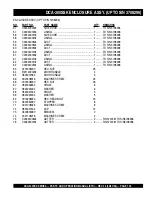
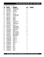
DCA-300SSK NAME PLATE  AND DECALS

NAMEPLATE AND DECALS

NO.

PART NO.

PART NAME

QTY.

REMARKS

ENGINE & RADIATOR GROUP

16

6360610304

DECAL; WATER ......................................................... 1............ S-1880

17

B9504000404

DECAL; WARNING .................................................... 2............ B90400040

18

B9504100104

DECAL; WARNING .................................................... 1............ B90410010

OUTPUT TERMINAL GROUP

24

0840614104

DECAL; GROUND ..................................................... 1............ S-2635

25

0840619904

DECAL; DANGER ...................................................... 1............ S-2731

26

B4551000103

DECAL; RECEPT. & CIRCT. BREAKER,B45100010 . 1............ S/N3691259 TO 3706720

26

C1551000803

DECAL; RECEPT. & CIRCT. BREAKER,C15100080 . 1............ S/N3706721AND ABOVE

27

B9511100304

DECAL; WARNING .................................................... 1............ B91110030

28

B9511100404

DECAL; WARNING .................................................... 1............ B91110040

29

B9531100504

DECAL; WARNING .................................................... 1............ B93110050

30

C0551000404

DECAL; 3-PHASE OUTPUT TERMINAL ................... 1............ C05100040

31

C1551000404

DECAL; 240/139 VOLT, C15100040 ........................... 2............ UP TO S/N3696506

31

9039209064

DECAL; START CONTACT, S4468 ............................ 1............ S/N3696507 AND ABOVE

BATTERY GROUP

32

0800689404

DECAL; + .................................................................. 1............ S-2090

33

0800689504

DECAL; - ................................................................... 1............ S-2091

34

C9505300004

DECAL; CAUTION ..................................................... 1............ C90530000

MUFFLER GROUP

35

B9504200004

DECAL; WARNING .................................................... 1............ B90420000

FUEL TANK GROUP

36

1320620904

DECAL; DIESEL FUEL ............................................. 1............ S-1756

37

6360620004

DECAL; FUEL DRAIN PLUG ..................................... 1............ S-1883

38

B9504500004

DECAL; WARNING .................................................... 1............ B90450000

Summary of Contents for Whisperwatt DCA-300SSK

Page 1: ...ND PARTS MANUAL PARTS LIST NO C2871300704 SERIAL NO 3708297 Revision 4 03 27 06 THIS MANUAL MUST ACCOMPANY THE EQUIPMENT AT ALLTIMES WHISPERWATTTM SERIES MODELS DCA 300SSK DCA 300SSK2 DCA 300SSK3 60 Hz GENERATORS ...

Page 2: ...PAGE 2 DCA 300SSK SERIES PARTS AND OPERATION MANUAL STD REV 4 03 27 06 ...

Page 3: ... based on the DCA 300SSK SERIES WHISPERWATT AC Generators Multiquip Inc reserves the right to discontinue or change specifications design or the information published in this publication at any time without notice and without incurring any obligations To find the latest revision of this publication visit our website at www mqpower com HERE S HOW TO GET HELP PLEASE HAVETHE MODEL AND SERIAL NUMBERON...

Page 4: ...ey Switch 37 39 Generator Start up Procedure Manual MPEC 40 Generator Start up Procedure Auto MPEC 41 Generator Shutdown Procedure 42 Maintenance 44 48 Trailer Maintenance 49 52 TrailerWiring Diagram 53 GeneratorWiring Diagram 54 EngineWiring Diagram S N 3696506 and Below 55 EngineWiring Diagram S N 3696507 to 3701673 56 EngineWiring Diagram S N3701674 and Above 57 EngineTroubleshooting 58 59 Gene...

Page 5: ...ed web parts order system or by fax qualify for the following extra discounts Ordered Standard Stock orders via orders 750 list and above Fax 3 10 Web 5 10 Special freight allowances when you order 10 or more line items via Web or Fax FedEx Ground Service at no charge for freight No other allowances on freight shipped by any other carrier Common nuts bolts and washers all items under 1 00 list pri...

Page 6: ...f s d a o l t n a t s n o c r o f e u l a v n a e m f o 5 2 0 n o i t a l u s n I F s s a l C A B d l e v e L d n u o S t e e f 3 2 t a d a o l l l u F 1 7 x o r p p A s n o i s n e m i D H x W x L m m 0 8 1 x 2 4 1 x 9 8 3 n i 1 7 x 6 5 x 3 5 1 t h g i e W t e N y r D g k 0 6 1 4 s b l 2 7 1 9 s n o i t a c i f i c e p S e n i g n E 2 e l b a T l e d o M 2 E 5 2 1 D 6 A S U S T A M O K 2 E 5 2 1 ...

Page 7: ... D 3 E L B A T e c n e r e f e R r e t t e L m m n i n o i s n e m i D r e t t e L e c n e r e f e R m m n i n o i s n e m i D A m m 5 7 0 1 n i 2 3 2 4 F m m 5 7 0 1 n i 2 3 2 4 B m m 5 1 0 1 n i 6 9 9 3 G m m 0 5 7 3 n i 4 6 7 4 1 C m m 0 4 6 n i 0 2 5 2 H m m 0 0 8 1 n i 8 9 0 7 D m m 5 8 5 n i 3 0 3 2 I m m 0 0 4 1 n i 2 1 5 5 E m m 5 1 0 1 n i 6 9 9 3 ...

Page 8: ... KILLED or SERIOUSLY injured if you do not follow directions You COULD be KILLED or SERIOUSLY injured if you do not follow directions You CAN be injured if you do not follow directions Gasoline engine exhaust gases contain poisonous carbon monoxide This gas is colorless and odorless and can cause DEATH if inhaled NEVER operate this equipment in a confined area or enclosed structure that does not p...

Page 9: ...the surrounding environment This generator other property or the surrounding environment could be damaged if you do not follow instructions NOTE NEVER tamper with the factory settings of the engine governor or settings Personal injury and damage to the engine or equipment can result if operating in speed ranges above maximum allowable CAUTION OVER SPEED CONDITIONS CAUTION ACCIDENTAL STARTING CAUTI...

Page 10: ...eath NEVER touch the hot exhaust manifold muffler or cylinder Allow these parts to cool before servicing engine or generator HighTemperatures Allowtheengine to cool before performing service and maintenance functions Contact with hot components can cause serious burns The engine of this generator requires an adequate free flow of cooling air NEVER operate the generator in any enclosed or narrow ar...

Page 11: ...to the equipment it is important to provide a good EARTH ground Article 250 Grounding of the National Electrical Code NEC providesguidelinesforpropergroundingandspecifies that the cable ground shall be connected to the grounding system of the building as close to the point of cable entry as practical The following safety recommendations should also be followed ALWAYS make sure generator is properl...

Page 12: ...gush out of the radiator causing severe scalding to any persons in the general area of the generator Coolant Drain Plug Removing the coolant drain plug while the engine is hot will result in hot coolant gushing out of the coolant drain plug therefore causing severe scalding to any persons in the general area of the generator Engine Oil Drain Plug Removing the engine oil drain plug while the engine...

Page 13: ...r less depending on type of terrain Place support blocks underneath the trailer s bumper to prevent tipping while parked Avoid sharp turns to prevent rolling DO NOT transport generator with fuel in tank Towing Transporting Safety To reduce the possibility of an accident while transporting the generator on public roads always make sure the trailer that supports the generator and the towing vehicle ...

Page 14: ...als Figures 2 3 These decals are provided for operator safety and maintenance information The illustration below and on the preceding pages show the decals as they appear on the machine Should any of these decals become unreadable replacements can be obtained from your dealer DCA 300SSK SERIES GENERATOR DECALS Figure 2 Generator Decals ...

Page 15: ...DCA 300SSK SERIES PARTS AND OPERATION MANUAL STD REV 4 03 27 06 PAGE 15 DCA 300SSK SERIES GENERATOR DECALS Figure 3 Generator Decals ...

Page 16: ...PAGE 16 DCA 300SSK SERIES PARTS AND OPERATION MANUAL STD REV 4 03 27 06 Figure 4 Typical Generator Grounding Application DCA 300SSK SERIES INSTALLATION ...

Page 17: ...d Also install the generator in a manner so that the exhaust will not be discharged in the direction of nearby homes The installation site must be relatively free from moisture and dust All electrical equipment should be protected from excessive moisture Failure to do will result in deterioration of the insulation and will result in short circuits and grounding Foreign materials such as dust sand ...

Page 18: ...he AC output section There are four leads A B C and D During light loads the power to the AutomaticVoltageRegulator AVR issupplied from the leads parallel connections of B C When loads increase the AVR switches and accepts power from leads A D The output of leads A D increase proportionally with load This of adding the voltages to each phase provides better voltage response during heavy loads The ...

Page 19: ... N M E T I N O I T P I R C S E D 1 y l b m e s s A r e l f f u M 2 y l b m e s s A e n i g n E 3 y l b m e s s A e r u s o l c n E 4 y l b m e s s A r o t a r e n e G 5 y l b m e s s A l a n i m r e T t u p t u O 6 y l b m e s s A y r e t t a B 7 y l b m e s s A k n a T l e u F 8 y l b m e s s A l e n a P l o r t n o C r o t a r e n e G 9 y l b m e s s A l e n a P g n i t a r e p O e n i g n E ...

Page 20: ...PAGE 20 DCA 300SSK SERIES PARTS AND OPERATION MANUAL STD REV 4 03 27 06 DCA 300SSK GENERATOR CONTROL PANEL Figure 6 Generator Control Panel S N 3701673 and Below S N 3701674 and Above ...

Page 21: ...by the engine controller s Over Crank Protection mode If the engine engages at a speed RPM s that is not safe the controller will shutdown the engine by initializing the Over Speed Protection mode Also the engine controller will shutdown the generator in the event of low oil pressure high coolant temperature low coolant level and loss of magnetic pickup These conditions can be observed by monitori...

Page 22: ...PAGE 22 DCA 300SSK SERIES PARTS AND OPERATION MANUAL STD REV 4 03 27 06 DCA 300SSK ENGINE OPERATING PANEL Figure 7 Engine Operating Panels S N 3701673 and Below S N 3701674 and Above ...

Page 23: ...ring normal operation of the generator stop the engine and fill the battery with distilled water to the specified level E Clogged Air Filter Lamp This lamp goes ON when the air filter is clogged If this lamp goes ON during normal operation of the generator stop the engine and replace the air filter 4 Oil Pressure Gauge During normal operation this gauge be should read in the GREEN zone When starti...

Page 24: ... 8 is provided with the following z Three 240 139V output receptacles 50 amp z Three circuit breakers 240V 50 amps z Two 120V GFCI receptacles 20 amp z Two 2 GFCI circuit breakers 120V 20 amps z Eight 8 output terminal lugs Output Terminal Panel Shown below Figure 8 is the OutputTerminal Panel lift up on the cover to gain access to receptacles and terminal lugs NOTE Terminal legs O and Ground are ...

Page 25: ...ted at least once a month Figure 9 G F C I Receptacle Each auxiliary receptacle is protected by a 50 amp circuit breaker These breakers are located directly above the GFCI receptacles Remember the load output current on all three receptacles is dependent on the load requirements of the UVWO terminals Turn the voltage regulator control knob Figure 11 on the control panel to obtain the desired volta...

Page 26: ...breakers to the OFF position prior to starting the engine DCA 300SSK SERIES OUTPUT TERMINAL PANEL FAMILIARIZATION Over Current Relay An over current relay Figure 13 is connected to the main circuit breaker In the event of an overload both the circuit breaker and the over current relay may trip If the circuit breaker can not be reset the reset button on the over cur rent relay must be pressed The o...

Page 27: ...MPERAGE The power factor of this generator is 0 8 See Table 5 below when connecting loads Three Phase Load When calculating the power requirements for 3 phase power use the following equation NOTE An inadequate size connecting cable which cannot carry the required load can cause a voltage drop which can burn out the appliance or tool and overheat the cable See Table 6 NOTE n o i t a r e p O e s a ...

Page 28: ...h P e e r h T V 8 0 2 V 0 2 2 V 0 4 2 V 6 1 4 V 0 4 4 V 0 8 4 e s a h P e l g n i S V 0 2 1 V 7 2 1 V 9 3 1 V 0 4 2 V 4 5 2 V 7 7 2 s g n i t a R e r e p m A r o t a r e n e G 8 e l b a T 1 W k V 9 3 1 V 0 4 2 V 7 7 2 V 0 8 4 0 2 4 4 1 3 8 2 7 2 4 0 4 8 8 2 7 6 1 4 4 1 3 8 0 6 2 3 4 0 5 2 7 1 2 5 2 1 0 8 6 7 5 3 3 3 9 8 2 7 6 1 0 0 1 9 1 7 7 1 4 1 6 3 8 0 2 0 2 1 3 6 8 0 0 5 3 3 4 0 5 2 0 4 1 7 0 ...

Page 29: ...he selected leg The ammeter and voltmeter gauges areonlyactivewhenthe UVWO terminals are in use NOTE Figure 15 Voltage Change Over Board 240V Configuration Maximum Amps Table 10 shows the maximum amps the generator can pro vide DO NOT exceed the maximum amps as listed s p m A m u m i x a M r o t a r e n e G 0 1 e l b a T l e d o M K S S 0 0 3 A C D s e i r e S e g a t l o V d e t a R s p m A m u m...

Page 30: ... selected voltage 3Ø 240V UVWOTerminal OutputVoltages 1 Jumperthevoltagechange overboardfor240Voperation as shown in Figure 20 Figure 21 UVWO Terminal Lugs 3Ø 240V Connections 2 Connect the load wires to the UVWO terminals as shown in Figure 21 3 Turn the voltage regulator knob Figure 22 clockwise to increase voltage output turn counterclockwise to decrease voltage output Use voltage regulator adj...

Page 31: ...iguration Figure 26 UVWO Terminal Lugs 3Ø 480V Connections 1Ø 480V UVWOTerminal OutputVoltages 1 Make sure the voltage change over board is jumpered for 480V operation as shown in Figure 25 2 Connect the load wires to the UVWO terminals as shown in Figure 27 1Ø 277V UVWOTerminal OutputVoltages 1 Make sure the voltage change over board is jumpered for 480V operation as shown in Figure 25 2 Connect ...

Page 32: ...e following requirements Figure 30 Double Fuel Tank System REFILLING THE FUEL SYSTEM The DCA300SSK series generators may if equipped with a trailer or skid have a double fuel tank system Figure 30 which consists of an internal generator fuel tank and a trailer mounted fuel tank It is also possible the generator can be equipped with a skid mounted fuel tank Figure 31 The skid type fuel system does ...

Page 33: ...nk Filling Order Figure 32 Only Fill on Level Ground ONLY use 2 diesel fuel when refueling NOTE NOTE Fuel from the secondary inner tank will eventually drain into the primary trailer tank Figure 31 Skid Type Fuel Tank System ALWAYS place trailer on firm level ground before refueling to prevent spilling and maximize the amount of fuel that can be pumped into the tank CAUTION REFUELINGTHE GENERATOR ...

Page 34: ...ure 35 Notice how the trailer filler tube level rises when the internal tank is filled 5 Figure 36 below reflects a full fuel system 6 Fuelfromtheenginereturnlinewilldrainintothesecondary internal fuel tank This fuel will eventually drain into the primary trailer tank in order to return to the engine Figure 36 Full Fuel System DO NOT OVER FILL fuel system Leave room for fuel expansion Fuel expands...

Page 35: ...negative battery terminal disconnected Air Cleaner Periodic cleaning replacement is necessary Inspect it in accordance with the Komatsu Engine Owner s Manual Fan BeltTension A slack fan belt may contribute to overheating or to insufficient charging of the battery Inspect the fan belt for damage and wear and adjust it in accordance with the Komatsu Engine Owner s Manual The fan belt tension is prop...

Page 36: ...the battery when connecting the battery NOTE Battery This unit is of negative ground DO NOT connect in reverse Always maintain battery fluid level between the specified marks Battery life will be shortened if the fluid level are not properly maintained Add only distilled water when replenishment is necessary DO NOT over fill Check to see whether the battery cables are loose Poor contact may result...

Page 37: ...LWAYS have adequate ventilation when operating Direct exhaust away from nearby personnel CAUTION LETHAL EXHAUST HAZARD NEVER manually start the engine with the main GFCI or auxiliary circuit breakers in the ON closed position WARNING STARTINGTHE GENERATOR 2 Make sure the the voltage change over board has been configured for the desired output voltage 3 Connect the load to the UVWO terminals or aux...

Page 38: ...igure 48 Frequency Meter Hz Figure 47 Engine Ignition Switch 10 Turn the ignition key to the START position Figure 47 and listen for the engine to begin cranking After the engine starts release the ignition key Figure 46 Engine Throttle Control 11 Once the engine has started let it run for 3 5 minutes then turn the throttle handle control Figure 46 to the HIGH position 7 Whenstartingthegeneratorin...

Page 39: ...mately 1800 RPM s 16 The coolanttemperaturegauge Figure53 willindicate the coolant temperature Under normal operating conditions the coolant temperature should be between 165 and 215 degrees Fahrenheit Green Zone Figure 53 Coolant Temperature Gauge WATER TEMP 0 4 8 kg cm2 ENGINE OIL PRESSURE Figure 55 Main Aux and GFCI Circuit Breakers ON 18 Place the main GFCI and aux circuit breakers in the ON p...

Page 40: ... Reset Manual switch in the Manual position to start the engine Figure 61 Once the engine starts let the engine run for 1 2 minutes Listen for any abnormal noises Figure 60 Engine Speed Switch Low 6 Oncetheengineiswarmandtheengineisrunningproperly place the engine speed switch in the HIGH position Figure 62 Figure 62 Engine Speed Switch High 7 Verify that the Engine Running statusLED ontheMPEC uni...

Page 41: ... means of a contact closure that is generated automatically by a transfer switch NOTE Starting Auto Mode Before connecting this generator to any building s electrical system a licensed electrician must install an isolation transfer switch Serious damage to the building s electrical system may occur without this transfer switch DANGER ELECTRICAL SYSTEM HAZARDS When connecting the generator to a iso...

Page 42: ... Switch High 3 Let the engine cool by running it for 3 5 minutes with no loadapplied 4 Place the Auto Manual Off Reset switch Figure 72 to the OFF Reset position Figure 72 Auto Manual Off Reset Switch 5 Verify that the all status LED on the MPEC display are OFF not lit 6 Remove all loads from the generator Emergency Shutdown Procedure 1 PUSH inward the RED emergency stop button located on the engi...

Page 43: ...DCA 300SSK SERIES PARTS AND OPERATION MANUAL STD REV 4 03 27 06 PAGE 43 NOTE PAGE ...

Page 44: ...f k c e h C X r e t l i F d n a l i O e n i g n E e c a l p e R 1 X y r e t t a B e c i v r e S X e d i s t u O d n a e d i s n I t i n U n a e l C X r e t l i F l e u F e g n a h C 2 X t n a l o o C k c e h C d n a r o t a i d a R n a e l C l e v e L n o i t c e t o r P X t n e m e l E r e t l i F r i A e c a l p e R X s t a t s o m r e h T t s e T X r o t a i d a R h s u l F s p m a l C d n a s ...

Page 45: ... may vary according to season and locations Always pour through the mesh filter RemovingWater from theTank After prolonged use water and other impurities accumulate in the bottom of the tank Occasionally remove the drain cock and drain the contents During cold weather the greater the empty volume inside the tank the easier it is for water to condense This can be reduced by always keeping the tank ...

Page 46: ... of the reserve tank then fill with coolant water mixture to between the full and low lines 15 Stop the engine wait for 3 minutes add tap water until the water level reaches near the water filer port then tighten the radiator cap Changing Oil 1 Make sure the oil is cool before changing 2 Set a container directly under the drain plug of the oil pan Loosen the drain plug slowly 3 Check the drained o...

Page 47: ...z If the engine has not been started for more than one year contact your Komatsu distributor to have engine overhauled 5 After replacing filter cartridge loosen air bleed plug 6 Loosen the knob of feed pump and pump it up and down until no bubbles come out with the fuel from air bleed plug 7 After bleeding the air tighten air bleed plug then push in the knob of feed pump and lock it in position 8 ...

Page 48: ...in hot climates there is no reason to apply power to jacket water heater However if the generator will be used in cold climates it is always a good idea to apply power to the jacket water heater at all times To apply power to the jacket water heater simply apply power to thejacketwaterheaterreceptacleviacommercialpowerusing an power cord of adequate size DCA 300SSK SERIES MAINTENANCE If the genera...

Page 49: ...and Trailersupportdevicewithmaximumpound requirement from the tongue of the trailer 7 Coupler Type of hitch used on the trailer for towing 8 Tire Size Indicates the diameter of the tire in inches 10 12 14 etc and the width in millimeters 175 185 205 etc The tire diameter must match the diameter of the tire rim 9 Tire Ply The tire ply layers number is rated in letters 2 ply 4 ply 6 ply etc 10 Wheel...

Page 50: ...s listed below Actuator Hydraulicsurgebrakingrequirestheinstallationofanactuator at the tongue of the trailer Remember the surge or push of the trailer toward the tow vehicle automatically synchronizes the trailer brakes with the tow vehicle brakes As the trailer pushes against the tow vehicle the actuator telescopes together and applies force to the master cylinder supplying hydraulic pressure to...

Page 51: ...res when they are hot Check inflation pressure weekly during use to insure the maximum tire life and tread wear Table 15 Tire Wear Troubleshooting will help pinpoint the causes and solutions of tire wear problems Suspension The leaf suspension springs and associated components Figure 75 should be visually inspected every 6 000 miles for signs of excessive wear elongation of bolt holes and loosenin...

Page 52: ... down Tighten each lug nut in 3 separate passes as defined byTable 17 3 After first road use retorque all lug nuts in sequence Check all wheel lug nuts periodically Figure 76 Wheel Lug Nuts Tightening Sequence DCA 300SSK SERIES TRAILER MAINTENANCE s t n e m e r i u q e R e u q r o T e r i T 7 1 e l b a T e z i S l e e h W s s a P t s r i F S B L T F s s a P d n o c e S S B L T F s s a P d r i h T ...

Page 53: ...DCA 300SSK SERIES PARTS AND OPERATION MANUAL STD REV 4 03 27 06 PAGE 53 DCA 300SSK TRAILER WIRING DIAGRAM Figure 77 Trailer Towing Vehicle Wiring Diagram ...

Page 54: ...PAGE 54 DCA 300SSK SERIES PARTS AND OPERATION MANUAL STD REV 4 03 27 06 DCA 300SSK GENERATORWIRING DIAGRAM Figure 78 Generator Wiring Diagram ...

Page 55: ...DCA 300SSK SERIES PARTS AND OPERATION MANUAL STD REV 4 03 27 06 PAGE 55 DCA 300SSK ENGINEWIRING DIAGRAM S N 3696506 AND BELOW Figure 79 Engine Wiring Diagram S N 3696506 and Below ...

Page 56: ...PAGE 56 DCA 300SSK SERIES PARTS AND OPERATION MANUAL STD REV 4 03 27 06 DCA 300SSK ENGINEWIRING DIAGRAM S N3696507TO 3701673 Figure 80 Engine Wiring Diagram S N 3696507 3701673 ...

Page 57: ...DCA 300SSK SERIES PARTS AND OPERATION MANUAL STD REV 4 03 27 06 PAGE 57 DCA 300SSK ENGINE WIRING DIAGRAM S N 3701674 AND ABOVE Figure 81 Engine Wiring Diagram S N 3701674 and Above ...

Page 58: ... c w o l h t i w l e u F l e u f d e i f i c e p s e h t e s U n o i t c e j n i e s o o l o t e u d k a e l l e u F t u n g n i n i a t e r e p i p t u n n e t h g i T g n i m i t n o i t c e j n i t c e r r o c n I t s u j d A n r o w t f a h s m a c l e u F e c a l p e R d e g g o l c e l z z o n n o i t c e j n I e l z z o n n o i t c e j n i n a e l C g n i n o i t c n u f l a m p m u p n o i...

Page 59: ...d e i f i c e p s e h t o t e c u d e R r o n r o w r e n i l d n a g n i r n o t s i P k c u t s e c a l p e r r o r i a p e R g n i m i t n o i t c e j n i t c e r r o c n I t s u j d A n o i s s e r p m o c t n e i c i f e D e c n a r a e l c p o t t s u j d A y a r g k r a d r o k c a l b r e h t i E d e v r e s b o s i s a g t s u a h x e d a o l r e v O d a o l e h t n e s s e L d e s u l e ...

Page 60: ... R V A s I y r a s s e c e n f i e c a l p e R r e i f i t c e R g n i t a t o R e v i t c e f e D e c a l p e r d n a k c e h C t u p t u O e g a t l o V w o L t c e r r o c d e e p s e n i g n e s I h g i H o t r e v e l e l t t o r h t e n i g n e n r u T e s o o l s n o i t c e n n o c g n i r i w s I r i a p e r d n a g n i r i w k c e h C R V A e v i t c e f e D y r a s s e c e n f i e c a l...

Page 61: ... l l i r g r o t a i d a r r i a p e r n a e l C n e p o s r o o D s r o o d e s o l C g n i k a e l t s u a h x E t r a p y t l u a f r o s t e k s a g r i a p e r e c a l p e R d e d a o l r e v o g n i e b r o t a r e n e G d a o l e c u d e r k c e h C e r u l i a f t a t s o m r e h T t a t s o m r e h t e c a l p e R d e k c o l b e k a t n i r i A s e k a t n i r i a l l a r a e l C e r u l...

Page 62: ... available items Examples include battery cables shims and certain washers and nuts Not Sold Separately Indicates that an item cannot be purchased as a separate item and is either part of an assembly kit that can be purchased or is not available for sale through Multiquip Thefollowingsectionexplainsthedifferentsymbolsandremarks used in the Parts section of this manual Use the help numbers foundont...

Page 63: ...OSE UPPER S N 3708297 AND ABOVE 1 6152621540 RADIATOR HOSE LOWER S N 3708297AND ABOVE 1 0605505030 FUEL CAP 1 0601850590 KEY FUEL CAP 1 0601820625 AUTOMATICVOLTAGE REGULATOR 1 0601810072 PILOT LAMP 2 0601810261 BULB PILOT LAMP 1 23S0311150M CAP RADIATOR UPTO S N 3708296 1 0602122200 UNIT OIL PRESSURE 1 0602123206 UNIT WATERTEMPERATURE 1 0602121052 CHARGING AMMETER 1 0601804887 CIRCUIT BREAKER OUTP...

Page 64: ...PAGE 64 DCA 300SSK SERIES PARTS AND OPERATION MANUAL STD REV 4 03 27 06 GENERATOR ASSY DCA 300SSK GENERATOR ASSY ...

Page 65: ...5 8201614003 COUPLING RING 1 16 0012116040 HEX HEAD BOLT 6 17 0042516000 LOCKWASHER 6 18 0012112040 HEX HEAD BOLT 12 18 0042512000 LOCKWASHER 12 19 C2130100103 STATOR ASSY 1 20 0226200430 RUBBER SEAL 1 21 8201323004 CLAMPER 1 22 0223300140 RUBBER SEAL 1 23 8201323103 CLAMPER 1 24 0221200350 RUBBER SEAL 1 25 0010110035 HEX HEAD BOX 2 25 0041210000 PLAINWASHER 2 26 C2132200003 COVER 1 27 0226000275 ...

Page 66: ...PAGE 66 DCA 300SSK SERIES PARTS AND OPERATION MANUAL STD REV 4 03 27 06 DCA 300SSK GENERATOR ASSY GENERATOR ASSY ...

Page 67: ...HEAD BOLT 8 40 0012112035 HEX HEAD BOLT 16 40 0042512000 LOCKWASHER 16 41 C3132300003 COVER FAN 1 S N3691259TO 3692208 41 C3132300014 COVER FAN 1 S N3692209 AND ABOVE 42 0010106030 HEX HEAD BOLT 1 42 0041206000 PLAINWASHER 1 42 0600815000 NUT 1 S N3692209 AND ABOVE 43 0605000012 RUBBER SUSPENSION 2 44 0030020000 HEX NUT 4 44 0040020000 LOCKWASHER 4 DCA 300SSK GENERATOR ASSY ...

Page 68: ...PAGE 68 DCA 300SSK SERIES PARTS AND OPERATION MANUAL STD REV 4 03 27 06 DCA 300SSK CONTROL BOX ASSY CONTROL BOX ASSY ...

Page 69: ...000 PLAINWASHER 4 S N 3691259TO 3706720 9 0601820625 AUTOMATICVOLTAGE REGULATOR 1 NTA 5A 2T 10 0027105016 MACHINE SCREW 4 11 0601820892 OVER CURRENT RELAY 1 TH N20HZKP 12 0027104016 MACHINE SCREW 2 13 C2274000103 CHANGE OVER BOARDVOLTAGE 1 14 8201852104 CHANGETERMINAL 10 15 0017108030 HEX HEAD BOLT 20 16 C2277200004 TERMINAL PLATE 3 17 8201853104 CHANGE PLATE 6 18 8201852504 HEX HEAD BOLT 13 19 08...

Page 70: ...PAGE 70 DCA 300SSK SERIES PARTS AND OPERATION MANUAL STD REV 4 03 27 06 DCA 300SSK CONTROL BOX ASSY CONTROL BOX ASSY CONT ...

Page 71: ...T VOLTAGE REGULATOR 1 RA20A2SE102BJ 2W 1K OHM 41 0601840121 KNOB 1 42 0601810161 PANEL LIGHT 1 V325070 42 0601810214 BULB 1 43 0207004000 HEX NUT 2 44 0601830710 SWITCH PANEL LIGHT 1 45 C2214600104 COVER 1 S N3691259TO 3706720 46 0027105016 MACHINE SCREW 4 S N3691259TO 3706720 47 C9221100004 HEX HEAD BOLT 2 47 0040008000 LOCKWASHER 2 47 0041208000 PLAINWASHER 2 47 505015300 SNAP RING 2 REPLACES 00...

Page 72: ...PAGE 72 DCA 300SSK SERIES PARTS AND OPERATION MANUAL STD REV 4 03 27 06 DCA 300SSK CONTROL BOX ASSY CONTROL BOX ASSY CONT ...

Page 73: ... 1 S N 3696507 AND ABOVE 65 0601824400 HOLDER 1 S N 3696507 AND ABOVE 66 0027104020 MACHINE SCREW 2 S N 3696507 AND ABOVE 67 0601823706 RELAY HE1ADC24V 1 S N 3696507 AND ABOVE 68 0027104015 MACHINE SCREW 2 S N 3696507 AND ABOVE 69 0601815402 TERMINAL BOARD TS144P 1 S N 3696507 AND ABOVE 70 0027104020 MACHINE SCREW 2 S N 3696507 AND ABOVE 71 ECU9988N300 400 CONTROLLER 1 REPLACES 0601827396 06022025...

Page 74: ...PAGE 74 DCA 300SSK SERIES PARTS AND OPERATION MANUAL STD REV 4 03 27 06 DCA 300SSK ENGINE RADIATOR ASSY S N 3697258 AND BELOW ENGINE RADIATOR ASSY S N 3697258 AND BELOW ...

Page 75: ...0605000011 RUBBER SUSPENSION 2 13 0030016000 HEX NUT 4 14 0040016000 LOCKWASHER 4 15 6152619720 RADIATOR 1 REPLACES 0602011946 16 6152619170 RUBBER SHEET 2 REPLACES 0605000490 17 0010012055 HEX HEAD BOLT 4 18 0030012000 HEX NUT 4 19 0040012000 LOCKWASHER 4 20 0041212000 PLAINWASHER 8 21 8195123104 BRACKET RADIATOR 2 22 0017112025 HEX HEAD BOLT 2 23 0017110025 HEX HEAD BOLT 2 24 6152611520 RADIATOR...

Page 76: ...PAGE 76 DCA 300SSK SERIES PARTS AND OPERATION MANUAL STD REV 4 03 27 06 DCA 300SSK ENGINE RADIATOR ASSY UPTO S N3697258 ENGINE RADIATOR ASSY UP TO S N3697258 ...

Page 77: ...41 0603320112 U BOLT 1 42 0038408000 HEX NUT 2 43 0268200700 HOSE 1 44 0605515132 HOSE BAND 2 45 C2358300103 CLAMPER ROD 1 46 0017110020 HEX HEAD BOLT 2 47 C2358300003 CLAMPER ROD 1 48 0017108020 HEX HEAD BOLT 1 49 0010016030 HEX HEAD BOLT 1 50 0040016000 LOCKWASHER 1 51 0041216000 PLAINWASHER 1 DCA 300SSK ENGINE RADIATOR ASSY UPTO S N3697258 ...

Page 78: ...PAGE 78 DCA 300SSK SERIES PARTS AND OPERATION MANUAL STD REV 4 03 27 06 DCA 300SSK ENGINE RADIATOR ASSY S N 3708270TO 3708296 ENGINE RADIATOR ASSY S N3691259 TO S N 3708296 ...

Page 79: ...OLT 2 18 0017110025 HEX HEAD BOLT 2 19 0602014549 RADIATOR HOSE 1 REPLACES 6152611520 20 6152611531 RADIATOR HOSE 1 REPLACES 0602014641 21 0726120911 RADIATOR HOSE 1 REPLACES 0602014541 22 0728100809 HOSE BAND 6 REPLACES 0602014056 24 0728100197 HOSE BAND 2 REPLACES 0602014058 25 0802081003 RESERVE TANK 1 26 0602010900 CAP RESERVE TANK 1 27 C2317100003 BRACKET RESERVE TANK 1 28 0017108020 HEX HEAD...

Page 80: ...PAGE 80 DCA 300SSK SERIES PARTS AND OPERATION MANUAL STD REV 4 03 27 06 DCA 300SSK ENGINE RADIATOR ASSY S N 3708270 AND ABOVE ENGINE RADIATOR ASSY S N 3708270 AND ABOVE ...

Page 81: ...070 BOLT HEX HEAD 4 8 0030020000 NUT HEX 8 9 004002000 WASHER SPRING 4 10 0041220000 WASHER PLAIN 8 11 C2311100504 BRACKET RADIATOR 2 12 0010112025 BOLT HEX HEAD 2 13 0040012000 WASHER SPRING 2 14 0041212000 WASHER PLAIN 2 15 0017110025 BOLT HEX HEAD 2 16 6152611530 HOSE RADIATOR 1 REPLACES 06020 14539 17 6125621540 HOSE RADIATOR 1 REPLACES 06020 14653 18 0726120911 HOSE RADIATOR 1 REPLACES 06020 ...

Page 82: ...PAGE 82 DCA 300SSK SERIES PARTS AND OPERATION MANUAL STD REV 4 03 27 06 ENGINE RADIATOR ASSY S N 3708270 AND ABOVE DCA 300SSK ENGINE RADIATOR ASSY S N 3708270 AND ABOVE ...

Page 83: ...0560 HOSE 1 36 06055 15170 HOSE BAND 1 37 02691 00650 HOSE 1 38 C23271 00103 PIPE BREATHER 1 39 00171 08020 BOLT HEX HEAD 2 40 06033 20112 UBOLT 1 41 02070 08000 NUT HEX HEAD 2 42 02682 00700 HOSE 1 43 06055 15132 HOSE BAND 2 44 C23583 01003 ROD CLAMPER 1 45 00171 10020 BOLT HEX HEAD 2 46 C23583 00003 ROD CLAMPER 1 47 00171 08020 BOLT HEX HEAD 1 48 00100 16030 BOLT HEX HEAD 1 49 00400 16000 WASHER...

Page 84: ...PAGE 84 DCA 300SSK SERIES PARTS AND OPERATION MANUAL STD REV 4 03 27 06 DCA 300SSK ENGINE OPERATING PANEL ASSY ENGINE OPERATING PANEL ASSY UP TO S N3701673 S N3701674 ...

Page 85: ...C2355300414 GOVERNOR ROD 1 S N 3691259TO 3701673 14 C2355300104 GOVERNOR ROD 1 S N 3701673 AND BELOW 15 0602180106 BALL JOINT 2 S N 3701673 AND BELOW 16 0030008000 HEX NUT 2 S N 3701673 AND BELOW 17 0207006000 HEX NUT 2 S N 3701673 AND BELOW 18 0041206000 PLAINWASHER 2 S N 3701673 AND BELOW 19 0041206000 PLAINWASHER 2 S N 3701673 AND BELOW 20 505015300 SNAP PIN 2 UPTO S N3701673 REPLACES 060501050...

Page 86: ...PAGE 86 DCA 300SSK SERIES PARTS AND OPERATION MANUAL STD REV 4 03 27 06 DCA 300SSK OUTPUTTERMINAL ASSY OUTPUT TERMINAL ASSY S N3691259 UP TO S N3691258 ...

Page 87: ...03 CIRCUIT BREAKER QOU120B 20A 2 S N 3706721 REPL 0601805313 10 0601805840 CIRCUIT BREAKER KM 52 265V 50A 3 S N 3691259TO 3706720 10 0601808804 CIRCUIT BREAKER QOU250B 50A 3 S N 3706721 AND ABOVE 11 C1261600204 BRACKET CIRCUIT BREAKER 1 S N 3691259TO 3706720 11 C3261600704 BRACKET CIRCUIT BREAKER 1 S N 3706721AND ABOVE 12 0223300200 RUBBER CUSHION 1 S N 3691259TO 3706720 12 0221200150 RUBBER CUSHI...

Page 88: ...PAGE 88 DCA 300SSK SERIES PARTS AND OPERATION MANUAL STD REV 4 03 27 06 DCA 300SSK OUTPUTTERMINAL ASSY OUTPUT TERMINAL ASSY S N3691259 UP TO S N3691258 ...

Page 89: ...1504 COVER OUTPUTTERMINAL 1 S N 3691259 AND ABOVE 26 0805015604 RUBBERWASHER 1 S N 3691259 AND ABOVE 27 0845054204 COLLER 2 S N 3691259 AND ABOVE 28 0017110040 HEX HEAD BOLT 2 S N 3691259 AND ABOVE 29 0601815324 TERMINAL BOARD TS22P 1 S N3696507 AND ABOVE 30 0027104020 MACHINE SCREW 2 S N3696507 AND ABOVE 31 0601850275 GROMMET 1 S N3696507 AND ABOVE 32 0601851780 GROMMET 2 S N3700674 AND ABOVE 34 ...

Page 90: ...PAGE 90 DCA 300SSK SERIES PARTS AND OPERATION MANUAL STD REV 4 03 27 06 DCA 300 SSK ACTUATOR ASSY ACTUATOR ASSY S N3701674 ...

Page 91: ...VER 1 REPLACES 0602211090 3 C1356200004 BRACKET ACTUATOR 1 4 0012310030 HEX HEAD BOLT 4 5 0010306035 HEX HEAD BOLT 4 5 0207006000 HEX NUT 4 5 0040006000 LOCKWASHER 4 5 0041206000 PLAINWASHER 4 6 0602211091 ROD 1 7 0602180190 BALL JOINT 2 8 0602211092 HEX NUT 2 9 0010106025 HEX HEAD BOLT 1 9 0207006000 HEX NUT 1 9 0041206000 PLAINWASHER 1 10 0010106025 HEX HEAD BOLT 1 10 0207006000 HEX NUT 1 10 004...

Page 92: ...PAGE 92 DCA 300SSK SERIES PARTS AND OPERATION MANUAL STD REV 4 03 27 06 DCA 300 SSK BATTERY ASSY BATTERY ASSY ...

Page 93: ...TTERY BAND 1 4 0805002904 BATTERY BOLT 2 5 0037808000 WING NUT 2 6 0040008000 LOCKWASHER 2 7 0041208000 PLAINWASHER 2 8 C2347600404 BATTERY CABLE 1 9 C2347600104 BATTERY CABLE 1 10 C2347600204 BATTERY CABLE 1 11 C2347600304 BATTERY CABLE 1 12 C2347200004 EARTH CABLE 1 13 0010010030 HEX HEAD BOLT 4 14 0030010000 HEX NUT 4 15 0845040414 TERMINAL CAP 2 16 0845041304 TERMINAL CAP 2 17 0602220204 BATTE...

Page 94: ...PAGE 94 DCA 300SSK SERIES PARTS AND OPERATION MANUAL STD REV 4 03 27 06 DCA 300SSK MUFFLER ASSY MUFFLER ASSY ...

Page 95: ... PIPE 1 S N 3708297 AND ABOVE 4 6150115751 GASKET 1 REPLACES 0602320142 5 7502356004 GASKET 1 S N 1337508TO 3691258 5 C1334200304 GASKET 1 S N 3691259TO S N 3708296 5 6150115751 GASKET 1 S N 3708297 ABOVE 6 0010312050 HEX HEAD BOLT 4 6 0030312000 HEX NUT 4 6 0040012000 LOCKWASHER 4 6 0041212000 PLAINWASHER 8 7 0010112055 HEX HEAD BOLT 4 7 0030012000 HEX NUT 4 7 0040012000 LOCKWASHER 4 7 0041212000...

Page 96: ...PAGE 96 DCA 300SSK SERIES PARTS AND OPERATION MANUAL STD REV 4 03 27 06 DCA 300SSK FUELTANK ASSY FUEL TANK ASSY ...

Page 97: ...R 1 FF 9 7 0802120604 PACKING 1 8 0605501050 UNIT FUEL 1 52000 KA9810 9 0602021155 PACKING 1 52391 KW3700 10 0027104010 MACHINE SCREW 5 S N 3691259 AND ABOVE 10 0022905015 MACHINE SCREW 5 S N 1337508TO 2691258 11 8195523104 TANK BAND 2 12 0805003414 PAD TANK BAND 4 13 0017108020 HEX HEAD BOLT 2 14 0037908000 HEX NUT 2 15 0222100300 TANK SHEET 6 16 0130206000 STREET ELBOW 1 17 3515512014 DRAIN PIPE...

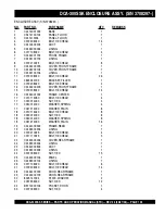
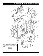
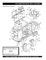
Page 98: ...300SSK ENCLOSURE ASSY UPTO S N 3708296 ENCLOSURE ASSY UP TO S N 3708296 THE SERIAL NUMBER MAY BE REQUIRED THE PART NUMBER ABOVE INDICATES DEFAULT COLOR OF ORANGE TO ORDER WITH DIFFERENT COLOR PLEASE ADD THE FOLLOWING LETTERS WITH THE PART NUMBER MQGR GRAY MQGRN GREEN MQW WHITE ...

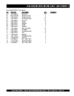
Page 99: ...1 10 C2494100104 LINING 1 11 0019208020 HEX HEAD BOLT 26 12 0845042703 FILLER BRACKET 1 13 0019208020 HEX HEAD BOLT 4 14 C2424200203 COVER FRONT FRAME 1 15 0019208020 HEX HEAD BOLT 14 16 C2434000102 CENTER FRAME 1 UPTO S N 1337973 16 C2434000112 CENTER FRAME 1 S N 1337974TO 3708296 17 0010114050 HEX HEAD BOLT 4 17 0030014000 HEX NUT 4 17 0040014000 LOCKWASHER 4 17 0041214000 PLAINWASHER 8 18 00101...

Page 100: ... SERIAL NUMBER MAY BE REQUIRED THE PART NUMBER ABOVE INDICATES DEFAULT COLOR OF ORANGE TO ORDER WITH DIFFERENT COLOR PLEASE ADD THE FOLLOWING LETTERS WITH THE PART NUMBER MQGR GRAY MQGRN GREEN MQW WHITE DCA 300SSK ENCLOSURE ASSY UPTO S N 3708296 ENCLOSURE ASSY UP TO S N 3708296 ...

Page 101: ...R 2 47 0025008025 MACHINE SCREW 2 48 C2464100002 ROOF PANEL 1 TO S N 3708296 48 C2494500004 LINING 1 TO S N 3708296 49 0800251701 FILLER COVER 1 50 0025006016 MACHINE SCREW 2 50 0042306000 LOCKWASHER 2 50 0042406000 PLAINWASHER 2 51 C2464200002 ROOF PANEL 1 TO S N 3708296 51 C2494500104 LINING 1 TO S N 3708296 52 0019208020 HEX HEAD BOLT 32 53 C2454200402 SPLASHER PANEL 1 UP TO S N 1337973 53 C245...

Page 102: ... SERIAL NUMBER MAY BE REQUIRED THE PART NUMBER ABOVE INDICATES DEFAULT COLOR OF ORANGE TO ORDER WITH DIFFERENT COLOR PLEASE ADD THE FOLLOWING LETTERS WITH THE PART NUMBER MQGR GRAY MQGRN GREEN MQW WHITE DCA 300SSK ENCLOSURE ASSY UPTO S N 3708296 ENCLOSURE ASSY UP TO S N 3708296 ...

Page 103: ...004 DUCT 1 TO S N 3708296 61 C2494400104 LINING 1 TO S N 3708296 62 C2454300104 DUCT 1 TO S N 3708296 62 C2494400304 LINING 1 TO S N 3708296 63 0207008000 HEX NUT 28 64 B9114000002 DOOR HANDLE 4 65 0825007362 DOOR HANDLE 3 66 0021806016 MACHINE SCREW 28 66 0030006000 HEX NUT 28 67 0845046904 HINGE 6 67 0845045004 WASHER 6 68 0845047004 HINGE 5 68 0845045004 WASHER 5 69 0019208020 HEX HEAD BOLT 25 ...

Page 104: ...6 DCA 300SSK ENCLOSURE ASSY S N 3708297 ENCLOSURE ASSY S N 3708297 THE SERIAL NUMBER MAY BE REQUIRED THE PART NUMBER ABOVE INDICATES DEFAULT COLOR OF ORANGE TO ORDER WITH DIFFERENT COLOR PLEASE ADD THE FOLLOWING LETTERS WITH THE PART NUMBER MQGR GRAY MQGRN GREEN MQW WHITE ...

Page 105: ... FRONT FRAME 1 15 00192 08020 BOLT HEX HEAD 14 16 C24340 01002 FRAME CENTER 1 17 00101 14050 BOLT HEX HEAD 4 17 00300 14000 NUT HEX 4 17 00400 14000 WASHER SPRING 4 17 00412 14000 WASHER PLAIN 8 18 00101 14040 BOLT HEX HEAD 8 18 00300 14000 NUT HEX 8 18 00400 14000 WASHER SPRING 8 18 00412 14000 WASHER PLAIN 16 19 C24440 00302 FRAME REAR 1 19 C24943 00204 LINING 1 20 00192 10025 BOLT HEX HEAD 4 21...

Page 106: ...6 ENCLOSURE ASSY S N 3708297 DCA 300SSK ENCLOSURE ASSY S N 3708297 THE SERIAL NUMBER MAY BE REQUIRED THE PART NUMBER ABOVE INDICATES DEFAULT COLOR OF ORANGE TO ORDER WITH DIFFERENT COLOR PLEASE ADD THE FOLLOWING LETTERS WITH THE PART NUMBER MQGR GRAY MQGRN GREEN MQW WHITE ...

Page 107: ... SCREW MACHINE 2 48 C24641 00402 PANEL ROOF 1 48 C24945 00804 LINING 1 49 08002 51701 COVER FILLER 1 50 00250 06015 SCREW MACHINE 2 50 00423 06000 WASHER SPRING 2 50 00424 06000 WASHER PLAIN 2 51 C24642 00502 PANEL ROOF 1 51 C24945 00904 LINING 1 52 00192 08020 BOLT HEX HEAD 32 53 C24542 01402 PANEL SPLASHER 1 54 00191 08065 BOLT HEX HEAD 6 54 00423 08000 WASHER SPRING 6 54 00424 08000 WASHER PLAI...

Page 108: ...6 DCA 300SSK ENCLOSURE ASSY S N 3708297 THE SERIAL NUMBER MAY BE REQUIRED THE PART NUMBER ABOVE INDICATES DEFAULT COLOR OF ORANGE TO ORDER WITH DIFFERENT COLOR PLEASE ADD THE FOLLOWING LETTERS WITH THE PART NUMBER MQGR GRAY MQGRN GREEN MQW WHITE ENCLOSURE ASSY S N 3708297 ...

Page 109: ...NE 28 66 00300 06000 NUT HEX 16 67 08450 46904 HINGE 6 67 08450 45004 WASHER 6 68 08450 47004 HINGE 5 68 08450 45004 WASHER 5 69 00192 08020 BOLT HEX HEAD 25 70 06018 50097 STOPPER 8 71 00254 08025 SCREW MACHINE 8 72 08450 31504 CAP 15 73 06005 00090 EMBLEM 2 74 00211 06016 SCREW MACHINE 4 75 C24645 00204 GUTTER 2 77 0019208020 HEX HEAD BOLT 4 78 C1425700004 RADIATOR PANEL 1 79 0019206015 HEX HEAD...

Page 110: ...PAGE 110 DCA 300SSK SERIES PARTS AND OPERATION MANUAL STD REV 4 03 27 06 DCA 300SSK RUBBER SEAL ASSY RUBBER SEAL ASSY ...

Page 111: ...EAL 6 2 0228901090 RUBBER SEAL 4 3 0228900650 RUBBER SEAL 2 4 0228901030 RUBBER SEAL 4 5 0229201400 RUBBER SEAL 4 6 0229201300 RUBBER SEAL 1 7 0228800705 RUBBER SEAL 2 S N3691259TO 3701673 7 0221200705 RUBBER SEAL 2 S N3701674 AND ABOVE 8 0228801200 RUBBER SEAL 2 9 0228100120 RUBBER SEAL 4 10 0228100510 RUBBER SEAL 4 DCA 300SSK RUBBER SEAL ASSY ...

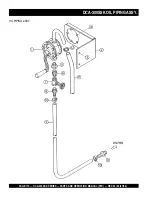
Page 112: ...PAGE 112 DCA 300SSK SERIES PARTS AND OPERATION MANUAL STD REV 4 03 27 06 OIL PIPING ASSY DCA 300SSK OIL PIPING ASSY ...

Page 113: ...KS 1 0602023040 PUMP 1 2 C2324400004 BRACKET PUMP 1 3 0017110025 HEX HEAD BOLT 2 4 0017106025 HEX HEAD BOLT 5 5 7522054204 BUSHING 1 6 0131506000 NIPPLE 1 7 0120006005 VALVE 1 8 3972027104 HOSE JOINT 2 9 0191600900 HOSE 1 10 0605515074 HOSE BAND 2 11 0193301200 HOSE 1 12 0605515004 HOSE BAND 1 DCA 300SSK OIL PIPING ASSY ...

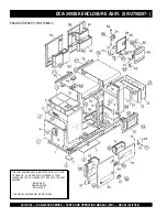
Page 114: ...PAGE 114 DCA 300SSK SERIES PARTS AND OPERATION MANUAL STD REV 4 03 27 06 DCA 300SSK NAMEPLATE AND DECALS NAMEPLATE AND DECALS ...

Page 115: ...2 C2551000004 DECAL SAFETY INSTRUCTIONS 1 C25100000 13 C2561101903 DECAL WHISPERWATT 300 1 C26110190 14 C9502400004 DECAL HIGH IDLE SPEED C90240000 1 S N3701674 15 0600500091 DECAL ENGINE CONTROLLER 1 S N3696507 ENGINE OPERATING PANEL GROUP 19 0840625004 DECAL PREHEAT LAMP S 3036 1 S N3691259TO 3701673 19 C155200013 DECAL OPERATING PANEL C15200001 1 S N3701674 20 0840625104 DECAL STARTER SWITCH S ...

Page 116: ...PAGE 116 DCA 300SSK SERIES PARTS AND OPERATION MANUAL STD REV 4 03 27 06 DCA 300SSK NAMEPLATE AND DECALS NAMEPLATE AND DECALS ...

Page 117: ...00803 DECAL RECEPT CIRCT BREAKER C15100080 1 S N3706721AND ABOVE 27 B9511100304 DECAL WARNING 1 B91110030 28 B9511100404 DECAL WARNING 1 B91110040 29 B9531100504 DECAL WARNING 1 B93110050 30 C0551000404 DECAL 3 PHASE OUTPUT TERMINAL 1 C05100040 31 C1551000404 DECAL 240 139VOLT C15100040 2 UPTO S N3696506 31 9039209064 DECAL START CONTACT S4468 1 S N3696507 AND ABOVE BATTERY GROUP 32 0800689404 DEC...

Page 118: ...PAGE 118 DCA 300SSK SERIES PARTS AND OPERATION MANUAL STD REV 4 03 27 06 DCA 300SSK NAMEPLATE AND DECALS NAMEPLATE AND DECALS ...

Page 119: ...AUTION 1 B90400030 43 B9531100604 DECAL WARNING 1 B93110060 44 C2561101003 STRIPE 1 45 C2561101603 STRIPE 1 46 C2561101303 STRIPE 1 TO S N 3708296 46 C2561102003 STRIPE 1 S N 3708297 AND ABOVE 47 C2561101404 STRIPE 1 TO S N 3708296 47 C2561102103 STRIPE 2 S N 3708297AND ABOVE 48 C2561101204 STRIPE 2 49 C2561101803 STRIPE 1 50 C2561101503 STRIPE 1 TO S N 3708296 50 C2561102203 STRIPE 1 S N 3708297 ...

Page 120: ...lcomponents f Paint chemicals andlubricants g Decalsandpaperproducts h Itemspurchasedinkits 7 The sender will be notified of any materialreceivedthatisnotacceptable 8 Such material will be held for five workingdaysfromnotification pending instructions If a reply is not received within five days the material will be returnedtothesenderathisexpense 9 Creditonreturnedpartswillbeissuedat dealer net pr...

Page 121: ...DCA 300SSK SERIES PARTS AND OPERATION MANUAL STD REV 4 03 27 06 PAGE 121 NOTE PAGE ...

Page 122: ...lanta Boise Dallas Houston Newark Quebec Canada Manchester UK RioDeJaniero BR Guadalajara MX HERE S HOW TO GET HELP PLEASE HAVE THE MODEL AND SERIAL NUMBER ON HANDWHEN CALLING PARTS DEPARTMENT 800 427 1244 or 310 537 3700 FAX 800 672 7877 or 310 637 3284 SERVICE DEPARTMENT 800 421 1244 FAX 310 537 4259 TECHNICAL ASSISTANCE 800 478 1244 FAX 310 631 5032 WARRANTY DEPARTMENT 888 661 4279 or 310 661 4...

Reviews: