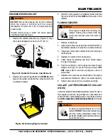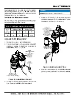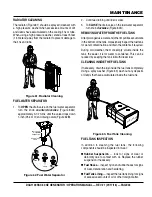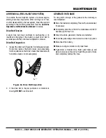
DCA1100SSC 60 HZ GENERATOR • OPERATION MANUAL — REV. #1 (01/17/18) — PAGE 53
DIAGNOSTIC DISPLAY
Figure 66. Diagnostic Display
The diagnostic display unit located inside the control box
on the generator (Figure 66) is designed to meet the needs
for instrumentation and control of electronically controlled
engine communication using the SAEJ1939 Controller
Area Network (CAN).
The Engine Control Unit (ECU750) used with this generator
diagnosis engine faults that arise with the engine control
system and the engine itself. Engine faults can be
determined by viewing the Diagnostic Trouble Codes (DTC)
The following definitions describe the controls and functions
of the Diagnostic Display Panel (Figure 66).
1.
Warning LED – When lit (AMBER), indicates a engine
parameter has exceeded its limits (minor fault). The
generator will still run in this condition.
2.
Emergency Stop LED – When lit (RED) indicates a
major fault has occured. This condition will shudown
the generator.
3.
Enter Key Button – Press this button to select the
parameter that is highlighted on the screen.
4.
Right Arrow Button – Press this button to scroll
through the screen either moving the parameter
selection toward the right or downward.
2
1
6
5
3
4
7
8
NOTICE
Reference the Cummins Operator’s Manual
for a complete listing of active fault codes and
countermeasures.
5.
Left Arrow Button – Press this button to scroll through
the screen either moving the parameter selection
toward the left or upward.
6.
Menu Button – Press this button to enter or exit menu
screens.
7.
Display Screen – Graphical backlight LCD screen.
Back lighting is controlled via menu or external
dimmer potentiometer. The display can show either a
single parameter or a quadrant display showing four
parameters simultaneously.
8.
Reset Button – To clear the display after a fault or
abnormal parameter has occured, press and hold this
button for one second. This will reset the display.
PROCEDURE
When the emergency shutdown system has shutdown the
engine, perform the following:
1. Open the right-side door (ECU side) on the generator.
Secure door with latch (Figure 67).
Figure 67. Opening Right-Side Door
Denyo
OPEN
RIGHT-SIDE
DOOR


