background image

1 0

High-Tech  Made in Switzerland

MS-MCDISK-D Rev. B

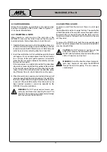
4. OPERATION

This chapter provides information about the use of the
PCMCIA cards and the LED indicators.

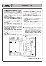
The illustration below identifies the items visible on the front
panel of the three MCDISK-D models (D-1, D-2 and D-3).

Fig. 4.1 Front panel of MCDISK-D-1

Fig. 4.2 Front panel of MCDISK-D-2

Fig. 4.3 Front panel of MCDISK-D-3

4.1 PCMCIA CARD TYPES

The MCDISK-D models have been designed to accept up to
four different PCMCIA card types:

• Type I:

Thickness 3.3 mm, no raised substrate area

• Type  II:

Thickness 5.0 mm, 48 mm wide raised substrate
area

• Type III:

Thickness 10.5 mm, 51 mm wide raised
substrate area

• Type IV: Thickness 14.2 mm, 51 mm wide raised

substrate area

Dependant on the MCDISK-D model, the usable card types
are:

MCDISK-D-1:
The lower card slot accepts all four types of cards. Due to the
front panel cut-out, the upper card slot only accepts type I - III
cards.
Type I and II cards in the lower and type I - III cards in the upper
slot can be inserted simultaneously. Type IV cards must be
inserted in the lower slot, fully occupying the space of both
slots.

MCDISK-D-2:
This single slot model accepts type I - IV cards.

MCDISK-D-3:
Only type I and II cards can be used.

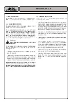
4.2 CARD POWER CONSUMPTION

For heat dissipation purpose the PCMCIA card current con-
sumption has to be considered.
The current consumption of a single card must never exceed
450mA. This corresponds to a maximum power consumption
of 2.25 W with 5V technology cards.
If two cards are used simultaneously, then the total current
consumption must never exceed 700mA (e.g. 450mA for the
first card, 250mA for the second card).
The total peak current must not exceed 800mA for a maximum
period of 1.5sec, independent of one or two cards being used.
When providing power for the

WARNING: Never exceed the current ratings indi-
cated above. If exceeded, serious damage and/or

failure of the MCDISK-D may result! Note also the
specifications of your AC direct plug-in transformer

unit.

Power Status InUse

CDISK

Power Status InUse

CDISK

Power Status InUse

CDISK

Summary of Contents for MS-MCDISK-D Series

Page 1: ...strial business and home applications with SCSI data input and or output TECHNICAL FEATURES Desktop case with compact dimensions 158x199x41 mm Interfaces PCMCIA JEIDA Memory Cards to any system with a...

Page 2: ...AL SCSI ID FEATURE MCDISK D 1 ONLY 6 2 5 TERMINATION 7 2 5 1 SCSI BUS TERMINATION 7 2 5 2 TERMINATOR POWER TERMPWR 7 2 6 PARITY 7 3 SCSI BUS AND POWER CONNECTION 8 3 1 SCSI BUS CONNECTION 8 3 2 POWER...

Page 3: ...t onto the case The unit has been damaged in any way e g through dropping The unit has been exposed to excess moisture or rain You suspect that the unit requires servicing or repair The power input ca...

Page 4: ...rating Environment Temperature 5 C 40 C Relative humidity non condensing 10 90 Physical Height 41 mm 1 6 Width 158 mm 6 2 Length 199 mm 7 85 Weight 0 60 kg 1 32 lbs 1 2 COMPATIBILITY MCDISK D operates...

Page 5: ...ID WARNING Ensure that each SCSI device has a unique SCSI ID number If not serious corruption of data and or failure of the host computer may result 2 SETTING UP This chapter and the next one provides...

Page 6: ...t jumper 7 Replace the top half of the case Note that it only fits correctly one way around 8 Replace the screws 9 Slide the gray plastic cover tabs back until they snap in place With the Dual SCSI ID...

Page 7: ...2 5 1 SCSI bus configuration 2 5 2 TERMINATOR POWER TERMPWR Generally the host computer is the only device on the SCSI bus required to provide TERMPWR for the bus Since the MCDISK D is a peripheral S...

Page 8: ...dealer or an authorised dealer of your host compu ter When connecting the SCSI bus cable s to the MCDISK D carefully align the connectors to avoid bending or damaging the connector pins WARNING The t...

Page 9: ...D is protected by an electronic fuse The fuse protects the MCDISK D in case of malfunction by disconnect ing the power input from the internal circuit If this happens the green power LED will go off a...

Page 10: ...II cards in the lower and type I III cards in the upper slot can be inserted simultaneously Type IV cards must be inserted in the lower slot fully occupying the space of both slots MCDISK D 2 This sin...

Page 11: ...en to ensure that the card is inserted correctly Follow these steps to insert the card 1 Orientate the memory card so that the printed surface e g with manufacturer name logo is up and the 68 pin conn...

Page 12: ...g start up power up or SCSI bus reset the MCDISK D performs some internal self tests When everything is okay the red and both yellow indicators will flash twice simultane ously to indicate proper star...

Page 13: ...l operating information stored in the MCDISK D is not lost when the power input to the MCDISK D is removed Under normal situations the battery should not need replacing throughout the life span of the...

Page 14: ...1 4 High Tech Made in Switzerland MS MCDISK D Rev B This page is intentionally left blank...

Page 15: ...1 5 High Tech Made in Switzerland MS MCDISK D Rev B This page is intentionally left blank...

Page 16: ...lity performance merchantability or fitness for a particu lar purpose In no event will MPL be liable for direct indirect special incidental or consequential damages resulting from any de fect in the p...

Reviews: