background image

UC-7122/7124 Hardware 

Hardware Connection Description 


3-4 

Connecting Data Transmission Cables 

This section describes how to connect the embedded computer to the network, serial devices, and serial COM 
terminal. 

Connecting to the Network 

Plug your network cable into the embedded computer’s Ethernet port. The other end of the cable should be 
plugged into your Ethernet network. When the cable is properly connected, the LEDs on the embedded 
computer’s Ethernet port will glow to indicate a valid connection. 

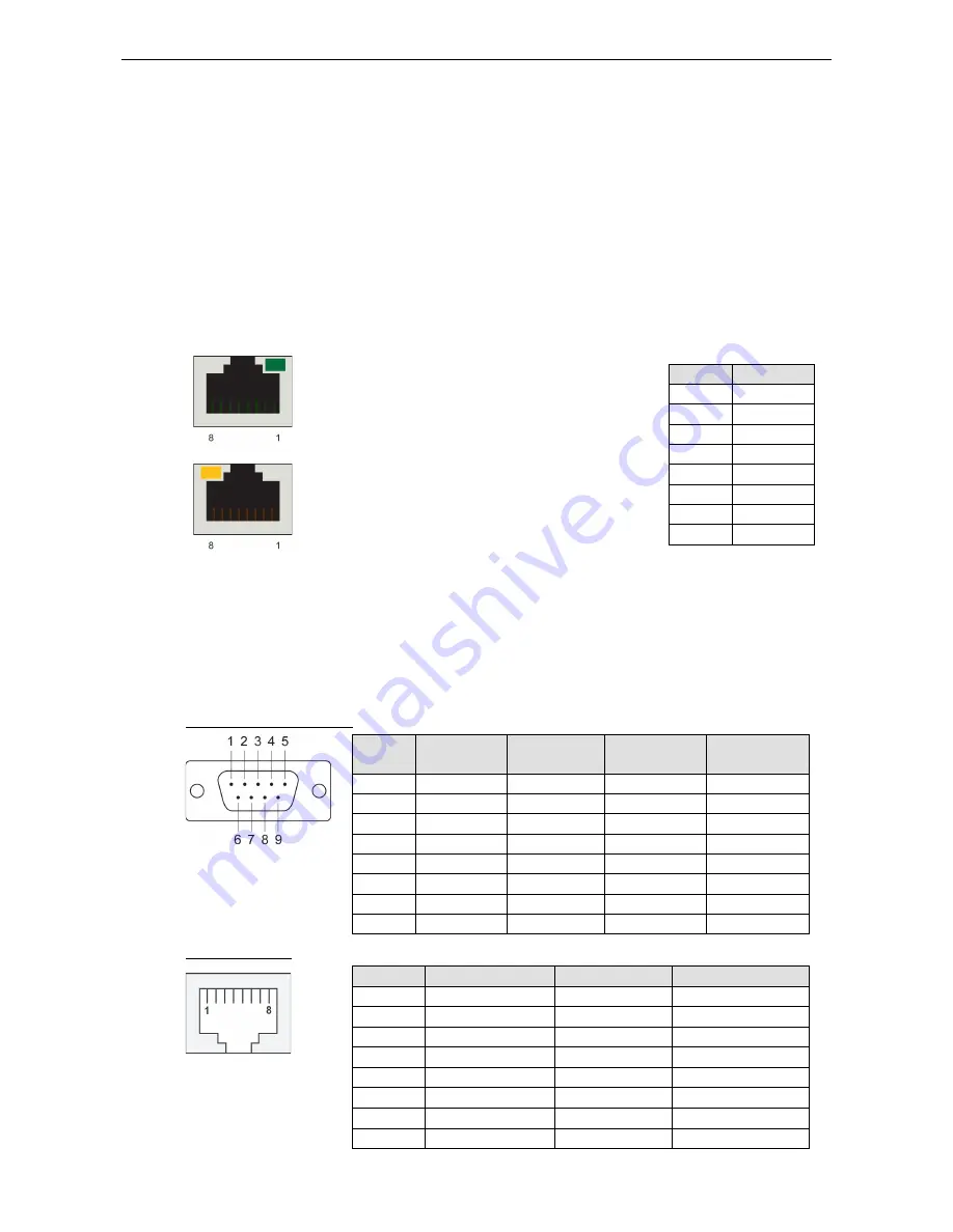
The 10/100 Mbps Ethernet LAN port uses 8-pin RJ45 connectors. The following diagram shows the pinouts for 
these ports. 


The LED indicator in the upper right corner glows a solid 
green color when the cable is properly connected to a 100 
Mbps Ethernet network. The LED will flash on and off when 
Ethernet packets are being transmitted or received. 

Pin 

Signal 

ETx+ 

ETx- 

ERx+ 

– 

– 

ERx- 

– 

– 


The LED indicator in the upper left corner glows a solid 
orange color when the cable is properly connected to a 10 
Mbps Ethernet network. The LED will flash on and off when 
Ethernet packets are being transmitted or received. 

Connecting to a Serial Device 

Use a serial cable to plug your serial device into the embedded computer’s serial port. The two serial ports on 
the UC-7122 use male DB9 connectors and are labeled P1 and P2. The four serial ports on the UC-7124 use 
RJ45 connectors and are labeled P1, P2, P3, and P4. All of the serial ports can be configured by software for 
RS-232, RS-422, or RS-485 communication. The pin assignments are shown in the following two tables: 

DB9 Male Port (UC-7122) 


Pin 

RS-232 

RS-422 

RS-485 

(4-wire) 

RS-485 

(2-wire) 

DCD 

TxDA(-) 

TxDA(-) 

– 

RxD 

TxDB(+) 

TxDB(+) 

– 

TxD 

RxDB(+) 

RxDB(+) 

DataB(+) 

DTR 

RxDA(-) 

RxDA(-) 

DataA(-) 

GND 

GND 

GND 

GND 

DSR 

– 

– 

– 

RTS 

– 

– 

– 

CTS 

– 

– 

– 


RJ45 (UC-7124) 


Pin 

RS-232 

RS-422 

RS-485 

DSR 

– 

– 

RTS 

TxD+ 

– 

GND 

GND 

GND 

TxD 

TxD- 

– 

RxD 

RxD+ 

Data+ 

DCD 

RxD- 

Data- 

CTS 

– 

– 

DTR 

– 

– 


Summary of Contents for UC-7122

Page 1: ...UC 7122 7124 Hardware User s Manual Edition 5 0 March 2017 www moxa com product 2017 Moxa Inc All rights reserved...

Page 2: ...s to this manual or to the products and or the programs described in this manual at any time Information provided in this manual is intended to be accurate and reliable However Moxa assumes no respons...

Page 3: ...2 3 UC 7124 2 4 LED Indicators 2 4 Reset Button 2 5 Real Time Clock 2 5 3 Hardware Connection Description 3 1 Installing the UC 7122 7124 3 2 Wall or Cabinet Mounting 3 2 DIN Rail Mounting 3 2 Wiring...

Page 4: ...ternal SD socket and one USB 2 0 host port for storage expansion to provide high performance communication and unlimited storage in a super compact palm size box The UC 7122 and UC 7124 are the right...

Page 5: ...deal communication platforms for simple data acquisition and protocol conversion applications In addition the RS 232 422 485 serial ports allow you to connect a variety of serial devices Taken togethe...

Page 6: ...M 32 MB Flash NOR Flash 16 MB OS pre installed Windows CE 5 0 Storage Storage Expansion SD slot Ethernet Interface LAN Auto sensing 10 100 Mbps ports RJ45 x 2 Magnetic Isolation Protection 1 5 kV buil...

Page 7: ...rrent UC 7122 170 mA 24 VDC 340 mA 12 VDC UC 7124 180 mA 24 VDC 360 mA 12 VDC Power Consumption UC 7122 4 1 W UC 7124 4 3 W Standards and Certifications Safety UL 60950 1 CSA C22 2 No 60950 1 03 EN 60...

Page 8: ...UC 7122 7124 Hardware Introduction 1 5 Hardware Block Diagrams UC 7122...

Page 9: ...UC 7122 7124 Hardware Introduction 1 6 UC 7124...

Page 10: ...vironments LED indicators help you monitor the performance and identify trouble spots and the reliable hardware platform allows you to devote your attention to developing your application In this chap...

Page 11: ...UC 7122 7124 Hardware Hardware Introduction 2 2 Appearance UC 7122 UC 7124...

Page 12: ...UC 7122 7124 Hardware Hardware Introduction 2 3 Dimensions UC 7122...

Page 13: ...is detected Off No SD card is detected LAN Orange 10 Mbps Ethernet link Green 100 Mbps Ethernet link Off Disconnected or short circuit TxD P1 P4 Green Serial ports P1 P4 transmitting data Off Serial...

Page 14: ...t the user directory and will NOT erase the user s data The reset button only loads a configuration file Real Time Clock The embedded computer s real time clock is powered by a lithium battery We stro...

Page 15: ...ting system provides powerful development tools that allow you to develop custom applications for remote operation of your device at low cost In this chapter learn how to connect the embedded computer...

Page 16: ...l devices to the embedded computer You should heed the following common safety precautions before proceeding with the installation of any electronic device Use separate paths to route wiring for power...

Page 17: ...hot to the touch Connecting the Power The DC source should be from a UL Listed Class 2 or Limited Power Source LPS external adaptor with output rated at 12 to 48 VDC 1 2 A minimum If the power is prop...

Page 18: ...ed or received Pin Signal 1 ETx 2 ETx 3 ERx 4 5 6 ERx 7 8 The LED indicator in the upper left corner glows a solid orange color when the cable is properly connected to a 10 Mbps Ethernet network The L...

Page 19: ...steps show you how to install an SD card in the UC 7122 7124 The SD slot is located on the right side of the UC 7122 7124 enclosure To install an SD card you must first remove the protective cover to...

Reviews: