background image

Mountain Models Tantrum 

50

5. 

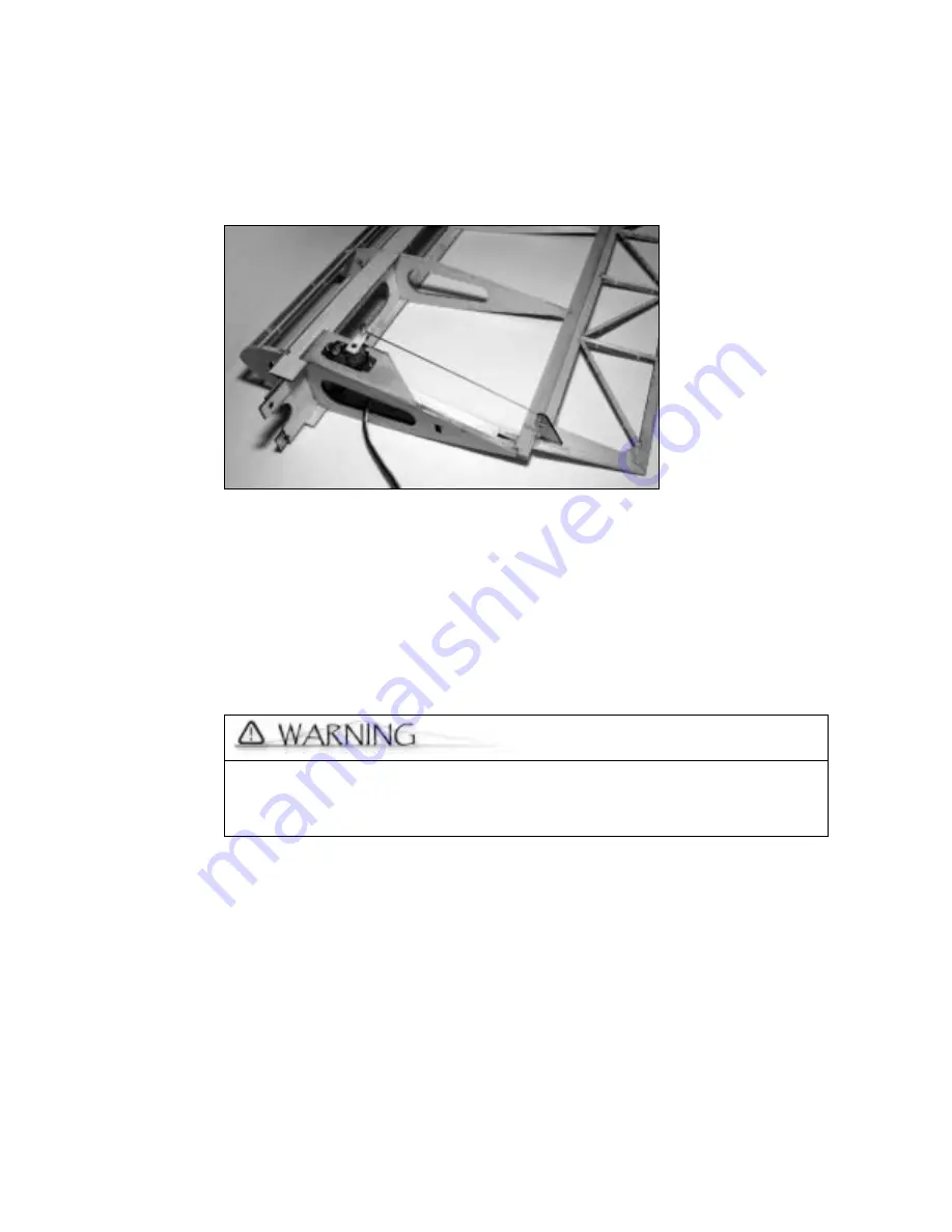
Attach the micro pushrod adjuster to the servo horn, but don't attach the horn to the 

servo yet.  

6. 

Run the non-bent side of the pushrod through the micro pushrod adjuster, attach the 

servo horn to the servo, and then screw the servo down using the screws that came 

with the servo. 


Step 12: Installing the Motor 

We recommend the GWS EPS300C-D for the motor. Refer to the GWS installation 

instructions for more information, if necessary.  

Installing the Motor 

1. 

Slide the gearbox through the motor mounts with the spinner facing forward. Make 

sure that it is FULLY seated. 

2. 

Drill a hole through the underside of the inner cowl, through the gear box and into the 

motor mount.  


The hole in the inner cowl should be at least 3/16" wide, so that the supplied 
motor retaining screw fit. Once you get through the cowl, stop with that drill 

bit and use a 1/16” drill bit to complete the hole through the gear box and 

the motor mounts. 

Summary of Contents for Tantrum

Page 1: ...Tantrum Specifications Wingspan 37in 94cm Length 37in 94cm Wing Area 370in2 2388cm2 Weight without battery 10oz 255g Wing Loading depending on battery 5 0 6 0oz ft2 ...

Page 2: ...lane is an aileron elevator rudder full house setup intended for the intermediate to advanced pilot It s intended to be flown in limited space situations without sacrificing its outstanding performance capabilities Sincerely Doug Binder doug mountainmodels com Mountain Models 6975 Blackhawk Place Colorado Springs CO 80919 www mountainmodels com Phone 719 592 1387 Fax 719 528 6125 For the most up t...

Page 3: ... with 200 grit sandpaper 90 triangle or small square to true the bulkheads and fuselage Covering material Sealing iron for applying the covering Clear packing tape for hinges 5 channel computer radio with aileron flap mixing or a 4 channel radio with a Y cable for the two aileron servos 4 or 5 channel receiver GWS EPS300C D motor with a 12x6 propeller 4 micro servos we recommend either the Hitec H...

Page 4: ...d Figure B 1 8 laser cut balsa sheet Figure C 1 16 laser cut balsa sheet Figure D 1 8 laser cut balsa sheet Figure E 1 16 laser cut balsa sheet Figure F 1 16 laser cut balsa sheet Figure G 1 16 laser cut balsa sheet Figure H 3 32 laser cut balsa sheet ...

Page 5: ...r cut balsa sheet Figure J 1 32 laser cut balsa sheet Figure K 1 16 laser cut plywood sheet Figure L 1 16 laser cut plywood sheet Figure M 1 64 plywood sheet Figure N 5 16 laser cut balsa for cowl Figure O 1 4 square x 18 balsa leading edge x 2 Figure P 1 64 plywood sheet ...

Page 6: ... work table and then cover them with wax paper to protect them Balsa is a lightweight and fragile wood so you do need to be careful with it however you will also need to use a little bit of force to make everything fit properly so don t be too timid Join all of your pieces using thin CA cyanoacrylate glue unless we tell you otherwise In general only a small amount of CA is necessary to glue parts ...

Page 7: ...tronics Step 15 Finish the kit up with the canopy batteries throws center of gravity and the landing gear Final Step On a calm day find a field without too many trees or light poles and go fly Trees and light poles REALLY like to munch on remote control planes We say this from experience trust us Step 1 Preparing Your Workspace for Assembly Before you begin assembling the Tantrum you must prepare ...

Page 8: ...ces are connected together you should be able to fly it around the room making airplane noises yes I do mean BEFORE you add the glue The pieces are pretty snug when you are trying to fit them together Use about the same amount of pressure as you would on a jigsaw puzzle unless of course you don t like jigsaw puzzles and tend to smash the pieces in in that case be MUCH more gentle then putting toge...

Page 9: ...it on your worktable with the edge you are working on lining up with the edge of the table Using one bar sander to hold the piece down use another bar sander to do the actual sanding While sanding try to go over the entire edge in a sweeping motion avoiding any part of the assembly that is to remain non beveled This will make sure that your bevel angle is even across the entire way Make sure that ...

Page 10: ...r the horizontal stabilizer 4 Once the parts are dry carefully remove them from the wax paper Assembling the Rudder Putting the pieces together 1 Remove the pieces shown in black from the balsa sheet 2 Position the pieces and begin connecting them together to form the rudder as shown in the following image and then glue all of the joints 3 Once the parts are dry carefully remove them from the wax ...

Page 11: ...nd begin connecting them together to form the two halves of the elevator Assembled Elevator Right Side The two halves of the elevator are identical to each other one is simply the opposite side of the balsa sheet In other words once the elevator halves are together simply flip one over so it is the mirror image of the other one 3 Glue the joints for each of the elevator halves using thin CA ...

Page 12: ...a sheet Figure B Putting the pieces together 1 Remove the Aileron 1 pieces shown in black from the balsa sheet Aileron 1 2 Position the pieces and then begin connecting them together to form an aileron Aileron Assembly 3 Glue all of the joints following the process described for the horizontal stabilizer 4 Once the parts are dry carefully remove them from the wax paper 5 Remove the Aileron 2 piece...

Page 13: ...the tail feathers and the ailerons you can begin assembling the wings The wings are not interlocking but do have guides to help you make sure things go together correctly The information within this section applies to building one wing at a time and then duplicating the entire process for the other wing But if you want to you can build both the wings at the same time You must be sure to make a rig...

Page 14: ...s the wing root rib into the slot next to the cutout on the vertical spar 4 Push the slot located on the rib you removed from Figure B known as the wing tip rib onto the tab at the outside edge of the vertical spar This is where you can begin assembling the second wing making sure that it s a mirror image of the first one Did I mention that this was important Wing tip rib from Figure B Wing root r...

Page 15: ...ng ribs are split across two different balsa sheets For the second wing you are going to use two ribs from Figure E and one rib from Figure G Putting the pieces together While you are still holding the vertical spar with the slots towards the ceiling match up each wing rib slot with the remaining cutouts and then slide them into place Wing ribs from Figure E ...

Page 16: ...ll slide the fuselage attachment pieces behind the vertical spar into the provided slots in the wing root rib 2 On the other wing slide the other fuselage attachment pieces in front of the vertical spar using the provided slot 3 Make sure that you line up the holes on the reinforcements Don t glue these joints together yet you ll glue everything after the spar caps are attached This is so that the...

Page 17: ...b is lined up with the other ribs and then glue all of the joints making sure that the ribs fit fully into both spars that both spars are touching the vertical spar and that everything is flush snug and square including the wing reinforcements The Tantrum is meant to be a lightweight plane so make sure you use the CA as sparingly as possible but you shouldn t sacrifice strength for weight Attachin...

Page 18: ...ing Edge For each wing you will need 1 trailing edge Figure D Putting the pieces together 1 Line up the trailing edge with the slots at the end of the wing ribs so that all of the slots and tabs fit together 2 Make sure that everything lines up push the trailing edge firmly against the ribs and then glue the joints Attaching the Leading Edge For each wing you will need 1 4 leading edge balsa stick...

Page 19: ... leading edge in place until the glue cures and cut the leading edge flush with the inner rib then sand the edge from root to wing tip in order to match the profile of the wing rib There will be extra wood overhanging the wing root that will need to be trimmed so that both sides are flush with the outside as shown below Attaching the Aileron Servo Mount For each wing you will need 1 plywood ailero...

Page 20: ...thin CA Make sure you notice to which side the rectangles are being glued This is really important since the servo mount is attached underneath the wing with the rectangular pieces facing inside the wings 2 Using the other servo screw reinforcement perform the same process as Step 1 using the other available hole on the servo mount 3 Mark a line 1 4 on the servo mount following the guide shown bel...

Page 21: ... of the lower spar cap and hold until the glue has cured 6 Using the balsa servo mount reinforcement from Figure H line it up on the servo mount at the point where the square side and the angled side meet Make sure it s perpendicular and butted up against the inside of the root wing rib and then glue the joints Attaching the Wing Reinforcements For each wing you will need Wing reinforcements 3 Lon...

Page 22: ...de Using one of the long wing reinforcement pieces butt it up against the trailing edge making sure that the fingers are meshed together with the short wing reinforcement piece you glued in Step 1 3 Glue the long wing reinforcement into place 4 Underside of the Wing Tip Side Using one of the long wing reinforcement pieces butt it up against the trailing edge and glue it into place 5 Topside of the...

Page 23: ...ou can begin assembling the fuselage This involves assembling the fuselage sides and bottom attaching the bulkheads and tail piece assembling and attaching the motor mount supports and finally attaching the motor mount itself Assembling the Fuselage Sides For each fuselage side you will need Fuselage pieces Figure I Matching fuselage pieces Figure H Each fuselage side is on a different balsa sheet...

Page 24: ...age side Additionally the piece labeled C should actually connect at the bottom of the back piece 3 Using the matching pieces on Figure H repeat Step 2 to create the other fuselage side 4 Glue all of the joints on both fuselage sides For additional strength you may want to flow CA into where the wings connect with the fuselage Assembling the Fuselage Bottom You will need all of the bulkhead pieces...

Page 25: ...e with the rear edge of the fuselage bottom matching the point and the cutout as shown in the following picture 2 Glue the fuselage tail in place Reinforcing Bulkhead F2 You will need to reinforce the F2 bulkhead using pieces you remove from these balsa sheets Bulkhead F2 Figure C Bulkhead Reinforcement Figure G ...

Page 26: ...nt Figure D Reinforcing the bulkhead 1 Position the top bulkhead reinforcement from Figure G onto the front of bulkhead F2 matching the curve and notches and then glue it into place 2 Position the F2 bulkhead into the slot on the fuselage bottom as shown in the following picture Top bulkhead reinforcement Front ...

Page 27: ...es and then glue it into place 5 Position the bottom bulkhead reinforcement from Figure H on the back of bulkhead F2 matching the reinforcement s legs with the fuselage cutout and then glue it in place 6 Position the bottom bulkhead reinforcement from Figure F over the top of the reinforcement piece you glued on in Step 5 match up the edges and then glue it into place Bottom bulkhead reinforcement...

Page 28: ... remove the excess from your fingers with acetone Wash your hands though if you touch the CA with acetone on your hands you run the risk of loosening the bond For additional strength you may want to flow CA into the slot under the F2 bulkhead since this is where the landing gear is going to attach later Attaching the Battery Mount Support to Bulkhead F3 The battery mount support attaches to bulkhe...

Page 29: ...lkhead F3 and then glue it into place making sure that it matches the following picture 2 Position the F3 bulkhead into the slot on the fuselage bottom as shown in the following picture For additional strength you may want to flow CA into the holes in bulkhead F3 these are going to be used for routing the pull pull cables later Rear battery mount support ...

Page 30: ...ame time using pieces you remove from these balsa sheets Bulkhead F4 Figure G Bulkhead F5 Figure G Bulkhead F6 Figure G Assembling the bulkheads 1 Before you begin assembling you need to flow thin CA around the lightening holes of the F6 bulkhead This is to strengthen it so that the Pull Pull cables do not cut into the wood 2 Position F4 F5 and F6 into the fuselage bottom slots as shown in the fol...

Page 31: ... while you do have to use some gentle pressure to get it to fit if you push too hard you may break something If something does break a little CA never hurt While we don t recommend using too much since it adds weight don t worry if you have to fix a piece or two while you are building it happens to the best of us Inserting the Servo Mounts and Attaching the Other Fuselage Side You need to insert t...

Page 32: ...lines up and that the servo mounts are in the opposing two slots on this side 3 Glue the joints on the second fuselage side back to the F6 bulkhead Reinforcing Bulkhead F3 You will need to reinforce the F3 bulkhead using one piece from Figure G Bulkhead reinforcement Figure G Reinforcing the bulkhead Position the top bulkhead reinforcement from Figure G on the back of bulkhead F3 matching the curv...

Page 33: ... the bulkhead between the fuselage sides inserting it into the rear most slots 2 Glue the bulkhead into place and then finish gluing the rest of the fuselage sides and rear joints Attaching the Bulkhead Stringer The bulkhead stringer goes from the F7 bulkhead back to the rear of the fuselage Stringer Figure D F7 Bulkhead F3 bulkhead reinforcement ...

Page 34: ...gn the trailing edges of the two wings Wing Alignment Brace Figure D Attaching the wing alignment brace You aren t going to glue the wing alignment brace into position until after you cover the fuselage It is described here for positioning purposes only From the outside of the fuselage sides slide the wing alignment brace through the fuselage body and into the slots just in front of bulkhead F3 Bu...

Page 35: ...s into place We recommend tacking the pieces in place and not gluing anything solidly yet This will give you some additional flexibility in the balsa while you are lining up the sides and bottom 3 Using thick CA place a small bead of glue along the bottom corners where the fuselage bottom sides and the F1 bulkhead meet We chose to use thick CA at the corners for its added strength These spots are ...

Page 36: ...longer motor mount support through the fuselage body and into the slots closest to bulkhead F2 and then slide the shorter support into the slots closest to bulkhead F1 2 Make sure that they are centered and flush with the fuselage sides and then glue into place Assembling and Attaching the Motor Mount 4 motor mount pieces Figure L Motor mount supports inside the fuselage ...

Page 37: ...utouts on the motor mount are facing towards the F2 bulkhead 5 Make sure that the rear of the motor mount is flush with the back of the larger motor mount support and then using thick CA glue it into place Attaching the Fuselage Top Sheeting The sheeting is the balsa sheet that covers the tops of the bulkheads and forms the upper skin of the fuselage Fuselage Top Sheeting Figure J Attaching the fu...

Page 38: ...ce the glue is dry remove the rubber bands Attaching the Cowl Sheeting The cowl sheeting is exactly like the fuselage sheeting but it only fits over the cowl area Cowl Sheeting Figure J Attaching the cowl sheeting 1 Form the sheeting over the tops of the F1 and F2 bulkheads lining up the smaller end with the F1 bulkhead and the larger end with the F2 bulkhead The cowl piece is already attached and...

Page 39: ...bulkhead so that the cowl pieces will fit flush when attached 3 Center the cowl pieces onto the F1 bulkhead and then glue them into place 4 Sand the front of the cowl to give it a nice rounded look shown in the Attaching the Cowl Sheeting picture previously Step 6 Assembling the Landing Gear Once you ve finished building the fuselage you can begin assembling and attaching the landing gear Necessar...

Page 40: ...g too snug or causing gaps 3 Locate the center of the landing gear wire and bend it into a 70 angle and then measure 3 4 from each end of the landing gear wire and bend a 125 angle into each See the following picture for reference 4 Insert the landing gear wire into the landing gear mount 5 Position the other plywood landing gear reinforcement over the top of the balsa and plywood landing gear ass...

Page 41: ...e pieces Mind you by sharp edges we don t mean pokey bits you ARE going to have to sand those we just mean non rounded bits The only things that you need to sand since you did the bevels previously are listed in the following table What piece What to sand Wings Sand the wing root and tip ribs to make sure that the stringers and leading edge are flush with the face of the ribs Lightly sand the conn...

Page 42: ... not across it as this will cause less strain on the wood and less chance of breaking the pieces Using a tack cloth carefully remove the balsa dust once you are done sanding Attaching the Canopy Mounts You need to attach the canopy mounts to the fuselage on the side that should open the other side will be hinged Canopy Mounts Figure F Canopy Mounts Figure H Attaching the canopy mounts 1 Glue one o...

Page 43: ...ring material since it is extremely lightweight and won t crush the fragile balsa when shrinking Following your covering material instructions cover the pieces in this order Do not shrink the covering until both sides of each part are covered This reduces your chances of twisting the surfaces Tail Feathers Bottom and then top of the horizontal stabilizer You don t want to cover the center where it...

Page 44: ...the elevator horizontal stabilizer slot Cut out the wing slots on both sides of the fuselage Cut out the aileron servo access holes right behind the wing slots Cut out the openings for the rear wing alignment piece Cut out only the top bottom and front Fold the covering into the opening and tack it down Cut out the vent underneath the servos for the rudder and elevator This is for cooling purposes...

Page 45: ...ed Item 2 Servos Not provided with kit Installing the servos When using Hitec HS 55 servos use the long thin arm with the small holes 1 Before you install the servos you should attach the micro pushrod adjusters to the outermost holes It s easier to do this before you actually install the servos since you ll have to remove the control horns Install the servos so that one is facing one way while th...

Page 46: ...s to the right of the fuselage Rudder Using the piece shown above insert the control horn through the slot on the rudder positioning the control horn so that it s coming through the rudder evenly on both sides Ailerons Using the pieces shown above insert one of the control horns so that its holes are facing where the wing will attach into the same side that has the aileron servo mount Repeat for t...

Page 47: ... sure that it is forward of the elevator and that it is perfectly centered and square to the centerline of the fuselage You can check that the horizontal stabilizer is perfectly centered by measuring the distance from the outermost point of the horizontal stabilizer trailing edge to the rear of the fuselage on both sides the numbers should match Attaching the Vertical Stabilizer 1 Sand the front o...

Page 48: ...t waterproof You will need to remove this coating where you tie off the thread to set the knot with CA To do this run the dull edge of a Xacto blade along the length of each thread 1 Tie one end of the thread to one of the cotter pins seal the knot with thin CA and then remove the extra material 2 Position a piece of clear scotch tape over the rear of the fuselage where the cables are going to ent...

Page 49: ...ing the cables you can cover the fuselage bottom just like you did all of the other pieces previously Step 11 Installing the Aileron Servos Next you are going to install the aileron servos These steps are for one aileron so you just need to repeat the process for the other aileron For each aileron servo you will need Clear packing tape 1 1 32 x 18 thin music wire for the tailskid and pushrods 1 Mi...

Page 50: ...or the motor Refer to the GWS installation instructions for more information if necessary Installing the Motor 1 Slide the gearbox through the motor mounts with the spinner facing forward Make sure that it is FULLY seated 2 Drill a hole through the underside of the inner cowl through the gear box and into the motor mount The hole in the inner cowl should be at least 3 16 wide so that the supplied ...

Page 51: ...sert locking nuts Bagged Parts 1 Motor and battery mount retaining screw Bagged Parts Battery Mount and Front Battery Retainer Figure L Attaching the wings 1 Position the wings so that the servos are on the underside and then slide the fuselage attachment pieces through the wing slots on both sides of the fuselage Hole through the inner cowl Hole through the gear box Front Battery Retainer Battery...

Page 52: ...he following pieces in order Wing Bolt Metal Washer Front Battery Mount Retainer Wing Washer Nut 5 Slide the battery mount into the rear battery retainer located in the center of the F3 bulkhead and then slide it back through the front battery retainer so that the tabs line up with the front battery retainer 6 Insert the motor retaining screw into the hole located on the battery mount This is to m...

Page 53: ...e fuselage wall as the receiver Connect the battery to and the motor to the ESC following the guides on the controller itself Step 15 Finishing the Kit Well you re almost there the end is in sight just a few more steps and you can go flying assuming the weather is cooperating Attaching the Tailskid This is one of those highly overlooked but extremely important pieces if you want your backend to re...

Page 54: ...py 1 Cut two pieces off of the Velcro strip matching the size of the Velcro in the canopy mounts 2 Line up the canopy sheet over the canopy area of the fuselage and determine where the Velcro should go once everything is lined up along all of the edges 3 Using the clear packing tape tape the side opposite the Velcro to the fuselage so that it will act as a hinge 4 Attach the Velcro that is going t...

Page 55: ...you may want to mix 50 flaps to elevator so that when the elevator goes up the flaps go down This will allow the Tantrum to perform very tight loops Setting the Center of Gravity The Center of Gravity CG will affect how the airplane recovers from a nose up or nose down condition pitch stability With the CG too far forward the plane will be quite stable but require a lot of up elevator to fly level...

Reviews: