


U S I N G M I D I E X P R E S S X T C O N S O L E
60
Filtering channelized messages
Each channel in the Channelized section has its
own filtering settings. Think of the channel
selection as letting you step through the 16
different filter combinations on each channel on a
particular port (as conceptualized in Figure 7-14).
Figure 7-14: The channel settings in the Filter window lets you have
“layers” of filtering. Each channel has its own filter settings.
☛
When “All” is selected as the channel,
adjusting the message check boxes affects the
filtering of the messages on every channel. Under
this circumstance, the check boxes have a third
state (a “hatched-out” box as shown in Figure 7-13)
to indicate that a message is both filtered on one or
more channels and not filtered on one of more
channels. When the check box contains an “X”, the
message is filtered on all channels and when it
contains a “check” the message is not filtered on any
channel. You may cycle through the “all not
filtered”, “all filtered” and “combination filtered”
states by adjusting the check box from “check” to
“X” to “box” and back.
You can use the + and - keys to scan up and down
through the 16 channels at any time in the Filter
window. This makes it easy to adjust the filter
setting for a particular type of message at one time
without having to shift focus between the channel
setting and the filter setting.
For example, suppose you wanted to filter the
MIDI Timing Clock messages being generated by a
drum machine connected to input 1. MIDI Timing
Clock messages are from a general class of MIDI
messages called “real time” messages. All real time
messages are from the even more general class of
“non-channelized” messages. So, first, you would
access the Filter window for the input 1 (see
“Changing a filter setting” on page 59). In the Non-
Channelized section, click the check box next to
Real time so a red “X” appears. This setting will
prevent MIDI Timing Clock messages from
passing through the port. The overall effect of this
setting will prevent Timing Clocks from being
routed to any outputs connected to input 1 or being
received by any MIDI software using In 1.
CHANNEL MAP WINDOW
The Channel Map window allows you to change
the MIDI channel of all messages passing through
an input or output port. You can “remap” the
channels in any way you wish. Remap only one
particular channel, any combination or all
channels. As with the filter settings, each port can
be configured to have independent channel
remapping settings. The MIDI Express XT defaults
to no channel remapping (meaning channel 1
maps to channel 1, channel 2 maps to channel 2,
etc.), and in most cases, this should be the desired
default.
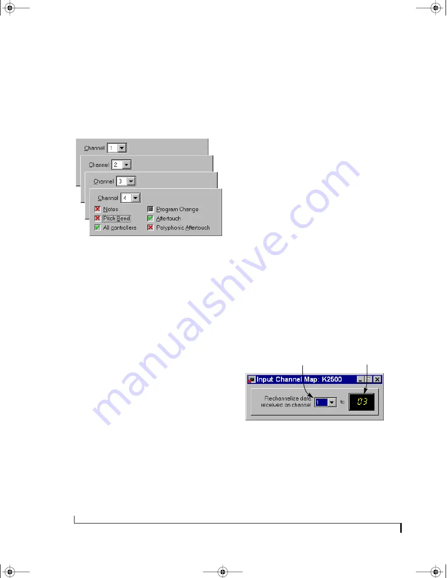
Figure 7-15: The Channel Map window for the input named “K2500”
showing channel 1 being mapped to channel 3.
Making a channel map setting
To remap channels of MIDI messages for a
particular port:
1
Click on the port’s icon in the MIDI Routing
window.
Original
channel
Remapped
channel
!USB Interfaces Manual Book Page 60 Tuesday, October 10, 2000 12:43 PM
Summary of Contents for micro express-USB
Page 1: ...C M Y CM MY CY CMY K...
Page 6: ...IV USB Interfaces Manual Book Page iv Tuesday October 10 2000 12 43 PM...
Page 7: ...All Users PartI ForAllUsers USB Interfaces Manual Book Page 5 Tuesday October 10 2000 12 43 PM...
Page 8: ...All Users USB Interfaces Manual Book Page 6 Tuesday October 10 2000 12 43 PM...
Page 28: ...XT Micro Users USB Interfaces Manual Book Page 26 Tuesday October 10 2000 12 43 PM...
Page 84: ...MPT AV Users USB Interfaces Manual Book Page 82 Tuesday October 10 2000 12 43 PM...
Page 142: ...Appendices USB Interfaces Manual Book Page 140 Tuesday October 10 2000 12 43 PM...


