


U S I N G M I C R O E X P R E S S C O N S O L E
41
2
With the port selected, click on the channel map
button above the selected port as shown in
Figure 6-7 on page 35.
3
Now, with the Channel Map window open,
select the channel you wish to remap on the left
side and enter the new (remapped) channel on the
right side.
You may make a remap setting for all 16 MIDI
channels.
You can use the + and - keys to scan up and down
through the 16 original channels at any time in the
Channel Map window. This makes it easy to enter a
number of remap channels at one time without
having to shift focus between the original channel
setting and the remap channel setting.
For example, you may want to use a keyboard that
transmits only on channel 1 to control a sound
module set to receive on some other channel, say 5.
Suppose the keyboard is connected to input 1 of
the Micro Express and the sound module is
connected to output 3. First, you would route input
1 to output 3 using the MIDI Routing window (see
“MIDI routing” on page 36). Next, you would
access the Channel Map window for input 1 in a
manner similar to accessing a Filter window. In the
Channel Map window, set the left channel selection
(the “original” channel) to “1” and type “5” into the
remap channel field on the right. This will cause
the Micro Express to change all events being
received from input 1 on channel 1 to channel 5.
Since this remapping happens before the routing to
output 3 (see “Micro Express MIDI processing” on
page 33.) the messages received by the sound
module will be on channel 5 even though the
keyboard originally transmitted them on
channel 1.
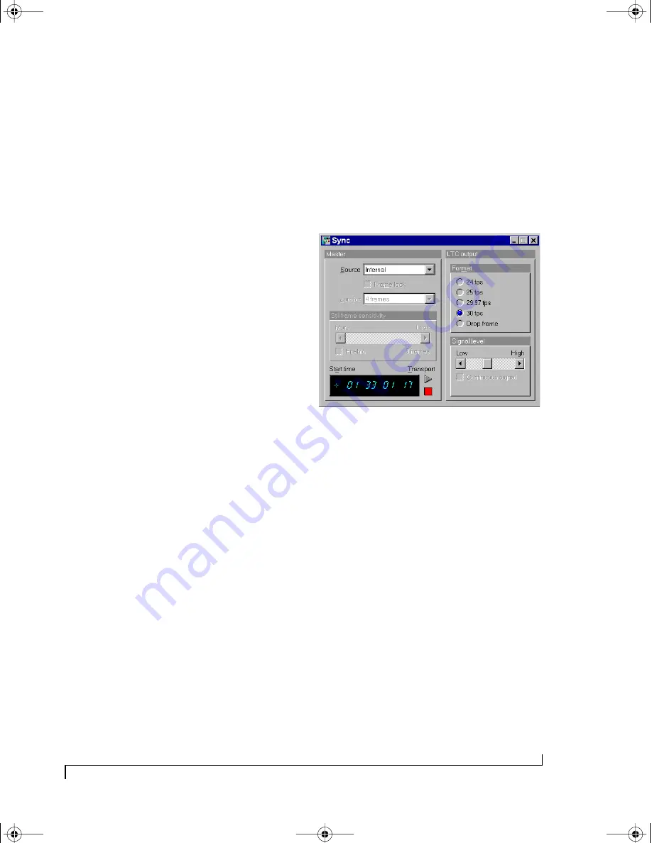
SYNC WINDOW
The Sync window is used to configure the Micro
Express’s many synchronization features. The
SMPTE stripe start time, frame rate, and audio
output level settings are made in this window.
Additionally, jam-sync (“free-wheeling”) settings
can also be made for the rare cases when you
encounter drop-outs while reading SMPTE.
Figure 6-16: The Sync window showing stripe settings of 30 fps from
01:33:01:17 at a medium signal level.
Converting SMPTE time code
The Micro Express will always convert received
SMPTE into MIDI Time Code (MTC). Converted
MTC is can be received by MIDI applications via
the “Sync” MIDI input port.
If you are new to SMPTE synchronization
If you are not familiar with the process of
synchronizing with SMPTE time code, see
Appendix B, “SMPTE Synchronization Basics”
page (145) before reading this section. It provides a
definition of SMPTE time code and an explanation
of how it is used for synchronizing MIDI devices to
audio and video equipment.
Source
The Source setting determines the time base and
time code master source. For a complete
explanation, see chapter 8, “SMPTE Synchroni-
zation” (page 71).
!USB Interfaces Manual Book Page 41 Tuesday, October 10, 2000 12:43 PM
Summary of Contents for micro express-USB
Page 1: ...C M Y CM MY CY CMY K...
Page 6: ...IV USB Interfaces Manual Book Page iv Tuesday October 10 2000 12 43 PM...
Page 7: ...All Users PartI ForAllUsers USB Interfaces Manual Book Page 5 Tuesday October 10 2000 12 43 PM...
Page 8: ...All Users USB Interfaces Manual Book Page 6 Tuesday October 10 2000 12 43 PM...
Page 28: ...XT Micro Users USB Interfaces Manual Book Page 26 Tuesday October 10 2000 12 43 PM...
Page 84: ...MPT AV Users USB Interfaces Manual Book Page 82 Tuesday October 10 2000 12 43 PM...
Page 142: ...Appendices USB Interfaces Manual Book Page 140 Tuesday October 10 2000 12 43 PM...


