background image

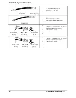
Appendix B - System Accessories 


B-4   


2005  MotorVac Technologies, Inc. 


Tee Adaptor 

For Single Line Fuel Injection Systems 


060-0440                 060-0450


2


HOSE CLAMPS.  USE WITH 060-
1000 THROUGH 060-1500. 


060-4501

Summary of Contents for CARBONCLEAN MCS 245

Page 1: ...Fuel System Service Diagnostic Equipment OPERATOR S MANUAL MCS 245 PDF VERSION...

Page 2: ...Procedure 4 15 Port Fuel Injection PFI Cleaning Procedure 4 19 Continuous Injection System CIS Setup Procedure 4 21 Continuous Injection System CIS Cleaning Procedure 4 25 Returnless System Setup Proc...

Page 3: ...panel the opening for the fuel reservoir and storage drawers for adaptors and other system accessories TIME DISPLAY CYCLE COMPLETE LED TIMER BUTTONS START BUTTON FUEL PRESSURE GAUGE PRESSURE REGULATOR...

Page 4: ...way System Warning LED Illuminates when The fuel detergent mixture runs out before run time expires Vehicle or unit pressure drop less than 5psi is detected Warning Alarm Sounds when the service is c...

Page 5: ...FRONT VIEW FUEL LEVEL WINDOW...

Page 6: ...the unit s cabinet holds the battery cables and vacuum pressure hose Output Hose red Connects to the input side of the vehicle s engine fuel system Return Hose black Connects to the return side of th...

Page 7: ...m Hose Forms a connection between the vacuum pressure from the vehicle engine and the vacuum pressure gauge on the unit Battery Cables Positive red and negative black battery connections 12 16 VOLTS D...

Page 8: ...back of the unit s cabinet contains an easy access area for the fuel filter along with storage slots for shop towels detergent bottles etc Please see Appendix A for information on replacing the unit...

Page 9: ...econds The solenoid remains open during the purge mode When the purge is complete the pump motor stops and the solenoid closes If the pressure drops below 4 PSI while the engine is running or the STAR...

Page 10: ...st is in progress The maximum time available is 60 minutes the minimum time available is 5 minutes The time is adjusted in increments of 5 minutes There is a 10 minute increment between 50 and 60 minu...

Page 11: ...g to governing environmental laws Never look directly into the air induction plenum or carburetor throat when the engine is operating Always plug or cap any open fuel lines during service Keep Cleaner...

Page 12: ...e of rich operation monitor the catalytic converter temperature and allow at least two minutes of operation at normal mixture subsequent to testing or service for converter cooling Catalytic converter...

Page 13: ...t the black battery clip to a solid ground point as far from the battery as possible 5 Fill the unit s reservoir with clean gasoline until the Fuel Level Window indicates 1 4 tank 6 Connect the unit s...

Page 14: ...t s fuel reservoir until the mixture of fuel and detergent reaches 1 4 tank according to the Fuel Level Window The unit is now ready to perform a cleaning service NOTE When adding detergent to reservo...

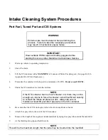
Page 15: ...d the solid steel or flex steel lines running from the fuel distributor to each individual injector easily identifies a Continuous Injection System The fuel distributor controls the amount of fuel spr...

Page 16: ...s been reached 3 Turn the Pressure Adjust regulator counterclockwise until the regulator is completely open 4 Attach the unit to the vehicle s battery by connecting the red battery clip to the positiv...

Page 17: ...essure loss can indicate a leak DIAGNOSTICS The vehicle s fuel system is now prepared to perform diagnostic tests if desired For instructions on how to perform these tests go to the next chapter title...

Page 18: ...hose Release the Fill Purge button WARNING Flammable Liquid can squirt out of pressurized lines when connecting or disconnecting Wear Safety goggles Obtain ZERO pressure before connecting or disconnec...

Page 19: ...s stops the flow of fuel from the vehicle to the carburetor during the cleaning process 18 As shown in the previous figure connect the output red hose from the unit to the adaptor going into the carbu...

Page 20: ...s the button to increase the time or the button to decrease the time until the Time LED displays 30 minutes Run time may be adjusted depending on the condition of the vehicle s fuel system 7 Start the...

Page 21: ...eads hoses and adaptors Return the vehicle s fuel system to its normal operating condition by re connecting the vehicle s fuel lines 13 Start the vehicle and verify that there are no leaks 14 Test dri...

Page 22: ...rature has been reached 3 Turn the Pressure Adjust regulator counterclockwise until the regulator is completely open 4 Attach the unit to the vehicle s battery by connecting the red battery clip to th...

Page 23: ...the unit is not used at this time 10 Start the vehicle and check connections for leaks Watch the Fuel Pressure gauge on the control panel to test system pressure since pressure loss could indicate a l...

Page 24: ...o relieve the pressure in the output red hose Release the Fill Purge button WARNING Flammable Liquid can squirt out of pressurized lines when connecting or disconnecting Wear Safety goggles Obtain ZER...

Page 25: ...o disconnect the fuel pump 17 As shown in the previous figure connect the output red hose from the unit to the adaptor on the pressure line going into the TBI unit 18 As shown in the previous figure c...

Page 26: ...button Make a note of the fuel pressure reading this is the true opening pressure of the vehicle s pressure regulator without vacuum assist when the engine is at normal operating temperature At this...

Page 27: ...m the output red hose Release the Fill Purge button 13 Loosen the vehicle s gas cap to relieve fuel tank pressure and then re install cap IMPORTANT Wrap a shop towel around pressure fittings before di...

Page 28: ...ature has been reached 3 Turn the Pressure Adjust regulator counterclockwise until the regulator is completely open 4 Attach the unit to the vehicle s battery by connecting the red battery clip to the...

Page 29: ...adaptor 060 2501 to both return side adaptors The return black hose on the unit is not used at this time 10 Start the vehicle and check connections for leaks Watch the Fuel Pressure gauge on the contr...

Page 30: ...o relieve the pressure in the output red hose Release the Fill Purge button WARNING Flammable Liquid can squirt out of pressurized lines when connecting or disconnecting Wear Safety goggles Obtain ZER...

Page 31: ...uel tank This forms a tank to tank loop making it unnecessary to disconnect the fuel pump 17 As shown in the previous figure connect the output red hose from the unit to the adaptor on the pressure li...

Page 32: ...e of the fuel pressure reading this is the true opening pressure of the vehicle s pressure regulator without vacuum assist when the engine is at normal operating temperature At this point refer to app...

Page 33: ...m the output red hose Release the Fill Purge button 13 Loosen the vehicle s gas cap to relieve fuel tank pressure and then re install cap IMPORTANT Wrap a shop towel around pressure fittings before di...

Page 34: ...een reached 3 Turn the Pressure Adjust regulator on the unit counterclockwise until the regulator is completely open 4 Attach the unit to the vehicle s battery by connecting the red battery clip to th...

Page 35: ...op adaptor 060 2501 to both return side adaptors The return black hose on the unit is not used at this time 10 Start the vehicle and check connections for leaks Watch the Fuel Pressure gauge on the co...

Page 36: ...eve the pressure in the output red hose Release the Fill Purge button WARNING Flammable Liquid can squirt out of pressurized lines when connecting or disconnecting Wear Safety goggles Obtain ZERO pres...

Page 37: ...nk This forms a tank to tank loop making it unnecessary to disconnect the fuel pump 17 As shown in the previous figure connect the output red hose from the unit to the adaptor on the pressure line goi...

Page 38: ...ssure and the Up Arrow LED stays illuminated without flashing This will clean the CIS system and filter the contaminants through the unit s filtering system 5 Release the Start button and continue to...

Page 39: ...LED on the control panel will illuminate and the unit s alarm will sound 11 DO NOT ALLOW CIS VEHICLES TO RUN OUT OF FUEL TURN OFF THE VEHICLE S IGNITION IMMEDIATELY UPON COMPLETION OF THE RUN CYCLE 1...

Page 40: ...ith single Pressure Line one coming from the fuel pump one going into the fuel rail 7 Add gasoline and detergent mixture to the reservoir See Reservoir Filling Vehicle Diagnostics WARNING Flammable Li...

Page 41: ...the fuel rail and fuel pressure line from tank The unit s RED output hose would connect to the ball valve of the TEE adaptor The BLACK return line is not used at this time You are now ready to perfor...

Page 42: ...ton to increases the time or the button to decreases the time until the Time LED displays 30 minutes Run time may be adjusted depending on the condition of the vehicle s fuel system Add additional run...

Page 43: ...connect the battery leads hoses and adaptors Return the vehicle s fuel system to its normal operating condition by re connecting the vehicle s fuel lines 12 Start the vehicle and verify that there are...

Page 44: ...el Volume Test Vacuum Test TBI Systems The following tests may be performed for this system Fuel System Pressure Test Fuel Volume Test Deadhead Test Leakdown Test Vacuum Test PFI Systems The following...

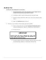
Page 45: ...c or the vehicle is slow to reach maximum pressure the vehicle s fuel filter may be clogged or its fuel pump may be weakening 4 Return to the appropriate previous chapter Fuel System Cleaning Procedur...

Page 46: ...o close it Re start the vehicle and slowly turn the gate valve clockwise to open it until the engine begins to labor slightly while idling Resume the test by repeating Step 3 4 Release the Fill Purge...

Page 47: ...l Pressure gauge on the unit This will give a good indication of the maximum pump output capabilities 5 Return to the appropriate previous chapter Fuel System Cleaning Procedures to continue the clean...

Page 48: ...Start Run button Press the button to decreases the time until the Time LED displays five minutes Press the Leak Test button on the unit s control panel Use the procedure above to re pressurize the sy...

Page 49: ...vehicle fuel lines Vacuum Test This test should be performed in conjunction with the cleaning process 1 Verify that Setup Steps 1 10 from the appropriate previous chapter have been completed for the s...

Page 50: ...ontainer with shop air to a minimum of 80 PSI Do not exceed 185 PSI 5 Shake the ICS container to aerate the mixture NOTE If the ICS container has too much cleaner in it there may not be enough air vol...

Page 51: ...ICS container and quickly pull the spray tube to the open end of the manifold near the throttle plate 13 Release the nozzle once the tip of the spray tube gets near the throttle plate NOTE Do not spra...

Page 52: ...be necessary to start the engine and continue with the cleaning process The continuation of the cleaning service will require the installation of the 6 inch spray tube to clean the Idle Air Control pa...

Page 53: ...and slide the Soak Tube into the manifold through the carburetor or TBI Spray the inside of the intake manifold with cleaner making sure to move the Soak Tube in a circular motion so that as much of...

Page 54: ...as close as possible to the throttle plate and insert the short Soak Tube into the vacuum hose in some cases it may be necessary to use the PCV hose as an inlet 4 While the engine is idling hold the I...

Page 55: ...pressed but unit will not build pressure With both hoses diconnected close the Pressure Regulator clockwise then open turn Hold Start button down until pressure builds Verify that filter and fittings...

Page 56: ...eanings to ensure maximum system performance and pump life Drain the Fuel Reservoir 1 Turn the Pressure Adjust regulator on the control panel clockwise until it is completely closed 2 Attach the unit...

Page 57: ...the unit s fuel reservoir with clean gasoline until the Fuel Level Window indicates 1 4 tank 4 Check the filter for leaks 5 Enter your initials the date and a check mark in the appropriate boxes of th...

Page 58: ...6 FUEL LINE MALE USE WITH SUITABLE HOSE CLAMPS 060 1200 2 GENERAL APPLICATIONS UTILIZING 3 8 FUEL LINE MALE USE WITH SUITABLE HOSE CLAMPS 060 1300 2 GENERAL APPLICATIONS UTILIZING 1 4 FUEL LINE FEMALE...

Page 59: ...L PRESSURE LINE MALE G M VORTEC M16 x 1 5 060 3105 1 TBI AND OR PORT FUEL PRESSURE LINE FEMALE G M VORTEC M16 x 1 5 080 3302 060 3300 O Ring 1 TBI AND OR PORT FUEL RETURN LINE MALE G M VORTEC M14 x 1...

Page 60: ...BLACK PORT FUEL PRESSURE LINE FORD 060 3605 1 1 2 FEMALE SPRING LOCK PORT FUEL PRESSURE LINE FORD 060 3901 080 3904 Clip 1 3 8 QUICK DISCONNECT PORT FUEL AND TBI 060 4200 1 5 16 MALE TBI AND OR PORT F...

Page 61: ...Appendix B System Accessories B 4 2005 MotorVac Technologies Inc Tee Adaptor For Single Line Fuel Injection Systems 060 0440 060 0450 2 2 HOSE CLAMPS USE WITH 060 1000 THROUGH 060 1500 060 4501...

Page 62: ...12MM 90 BANJO FITTING CIS OR EFI SYSTEMS IN CONJUNCTION WITH 060 1900 060 1901 060 1902 060 2402 2 14MM BANJO FITTING BMW AND LATE MODEL VW PRESSURE LINE 060 3304 080 3302 O Ring 1 USED WITH MV0601700...

Page 63: ...PORT FUEL AND TBI 060 4300 1 3 8 TBI AND OR PORT FUEL GM CHRYSLER JEEP EAGLE 060 1900 060 1901 060 1902 Bolt Washer Nut 2 6 2 CONNECTS 12MM BANJO FITTINGS FOR DIAGNOSTICS AND OR CREATING A LOOP 060 27...

Page 64: ...Female Side Late Model Mitsubishi Products Also includes Chrysler Imports various Kia Suzuki Hyundai Gas Powered Models 060 2310 Female Side Bubble Flare Type Adapter 14 mm x 1 5 Common Applications I...

Page 65: ...E WITH 14MM THREADS EUROPEAN CARS INLET AND OR RETURN MAY BE USED WITH 060 2700 CIS SYSTEMS MERCEDES AUDI A 6 060 2600 19MM WRENCH SIZE WITH 16MM THREADS EUROPEAN CARS INLET AND OR RETURN MAY BE USED...

Page 66: ...ader valve with Viton seal Qty 1 Top valve O ring Qty 2 Neck base O ring Qty 2 Spray Nozzle Qty 5 6 Spray tube Qty 5 30 spray tube Qty 5 Valve with 9 siphon tube Qty 2 Available Parts not included in...

Page 67: ...ess Power 030 0193 3 8 Compression Nut Ni Hose to Machine 050 0095 Filter 10 Micron Baldwin BT839 10 050 0007 Lens Pressure Gauge 3 inch 200 8012 Pressure Gauge Assembly 3 inch 050 1910 Lens Vacuum Ga...

Page 68: ...00 8036 Drawer assembly Plastic Black 050 0018 Solenoid 2 way Normally Closed 200 7006 Pressure regulator assembly 200 8031 Tuthill Pump Assembly 200 8239 Operators Manual 200 8300 Quick Reference Car...

Reviews: