VIP1002E Installation Guide 2
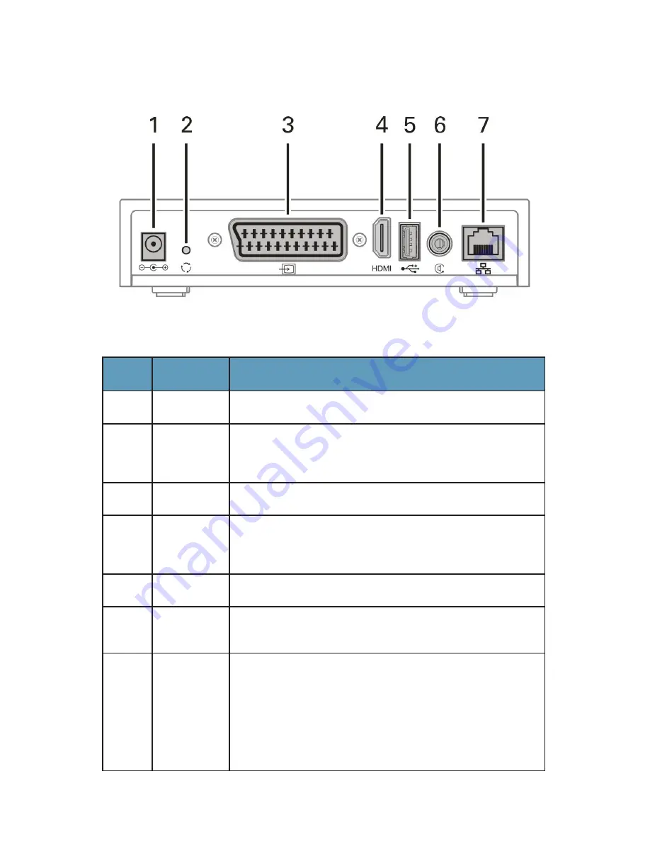
Figure 2: Rear Panel
Key
Item
Function
1
Power
Connector for the DC power adapter.
2
Reset
Reboots the VIP1002E, and resets all functions to the
original factory settings. Use only when directed by service
provider personnel.
3
Video Out
SCART video output to a TV, VCR, or other device.
4
HDMI
Connects to a high-definition TV or home theater receiver
with an HDMI input (for a DVI input use an HDMI-to-DVI
adapter).
5
USB
USB 2.0 connector.
6
Digital
Audio
Digital S/PDIF audio connection.
7
Ethernet
RJ-45 network connection for digital signal from your
service provider.
Note: There are two Ethernet LEDs, one for
Link
and one
for
Activity
. The Link LED illuminates when an Ethernet
cable is plugged into the VIP1002E set-top box and the
Ethernet network is up. The Activity LED blinks whenever
traffic is transmitted or received on the Ethernet interface.
Rear Panel
The following illustration shows the rear panel of the VIP1002E.
Summary of Contents for VIP1002E
Page 1: ...VIP1002E Installation Guide ...
Page 2: ......
Page 22: ...13 VIP1002E Installation Guide Notes ...
Page 23: ......
Page 24: ...577192 001 a 02 10 Visit our website at www motorola com ...


