Quick Reference Guide
9
6.
Mark the surface through the three holes on the bottom of the cradle, or use
the mounting template to determine the location of the screw holes.
7.
Pre-drill holes to accommodate three 1.5" #8 Phillips
???
head screws.
8.
Attach the cradle securely to the surface.
9.
Place the scanner in the cradle.
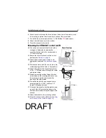
Mounting the STB2000-F on the Forklift
10.
Consult an environmental health and safety
manager to determine an appropriate
mounting location within the recommended
15" reach envelope.
11.
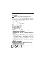
Ensure the converter knob is in the correct
position (see
Caution on page 6
).
12.
Attach the host and power cables to the
appropriate ports (see
Connections on page
7
).
13.
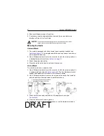
Position the cradle with the screw holes in the
cradle aligning with the holes in the isolators.
14.
Attach the cradle to the bracket using three
8-32 x 1.5" Phillips screws through the cradle
and isolator holes.
15.
Mark the mounting surface through the four
screw holes on the mounting bracket, or use
the mounting template to determine the
location of the screw holes.
16.
Pre-drill holes into the mounting surface to
accommodate four 1/4-20, minimum 1.0"
length, Phillips head screws.
17.
If desired, thread cable ties through the holes
on each side of the bracket and secure the
host and power cables along the edges of the
bracket.
18.
Attach the bracket to the mounting surface.
19.
Place the scanner in the cradle (see
Inserting
the Scanner in the Cradle on page 10
).
15" Radius
Side View, Standing
Top View
Side View, Seated
Reach Envelope
15" Radius
15" Radius
DRAFT

