


MOTOMESH DUO 2.1 4300 Users Guide
May 2008
3-3
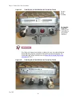
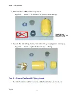
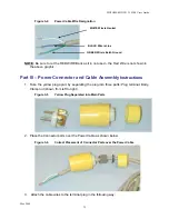
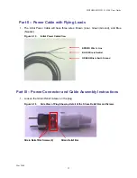
Figure 3-4
Power Cable Wire Designation
NOTE:
Be sure to cut the RED WIRE Back as it in not used – the Red Wire is not shown in
the above graphic.
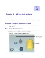
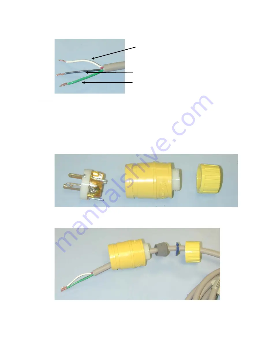
Part III – Power Connector and Cable Assembly
Instructions
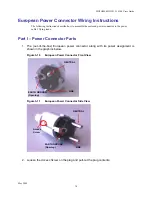
1. Take the yellow plug apart, by separating the plug into three parts: Plug terminal, Body,
Clamp nut (shown from left to right).
Figure 3-5
Yellow Plug Separated into Main Parts
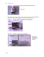
2. Place the Connector parts over the Power Cable as shown below.
Figure 3-6
Correct Placement of Connector Parts over the Power Cable
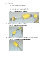
3. Attach the cable wires to the terminal plug in the following way:
WHITE Wire is Neutral
GREEN Wire is Earth Ground
BLACK Wire is Line
Summary of Contents for MOTOMESH Duo 4300-49
Page 1: ...MOTOROLA MOTOMESH DUO 2 1 4300 Users Guide May 2008 ...
Page 2: ...MOTOMESH DUO 2 1 4300 Users Guide May 2008 ii This page intentionally left blank ...
Page 4: ...MOTOMESH DUO 2 1 4300 Users Guide May 2008 iv This page intentionally left blank ...
Page 8: ...May 2008 viii Blank page intentionally left blank ...
Page 12: ...List of Tables May 2008 xii This page intentionally left blank ...
Page 14: ...List of Procedures May 2008 xiv This page intentionally left blank ...
Page 22: ...Chapter 1 Product Introduction May 2008 1 8 This page intentionally left blank ...
Page 36: ...Chapter 2 Infrastructure Device Installation May 2008 2 14 This page intentionally left blank ...
Page 52: ...Chapter 3 Wiring Instructions May 2008 3 16 Figure 3 35 Finished Power Connector ...
Page 74: ...Chapter 6 Customer Service May 2008 6 4 This page intentionally left blank ...
Page 90: ...Glossary May 2008 Glossary 2 This page intentionally left blank ...


