


Electrical Specifications
Technical Data
MC68HC908GP32
•
MC68HC08GP32
—
Rev. 6
372
Electrical Specifications
MOTOROLA
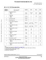
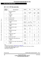
23.8 5.0-V Control Timing
Characteristic
(1)
1. V
SS
= 0 Vdc; timing shown with respect to 20% V
DD
and 70% V
DD
unless otherwise noted.
Symbol
Min
Max
Unit
Frequency of operation
(2)
Crystal option
External clock option
(3)
2. See
23.17 Clock Generation Module Characteristics
for more information.
3. No more than 10% duty cycle deviation from 50%
f
OSC
32
dc
(4)
4. Some modules may require a minimum frequency greater than dc for proper operation.
See appropriate table for this information.
100
32.8
kHz
MHz
Internal operating frequency
f
OP
(f
BUS
)
—
8.2
MHz
Internal clock period (1/f
OP
)
t
CYC
122
—
ns
RST input pulse width low
(5)
5. Minimum pulse width reset is guaranteed to be recognized. It is possible for a smaller pulse
width to cause a reset.
t
IRL
50
—
ns
IRQ interrupt pulse width low
(6)
(edge-triggered)
6. Minimum pulse width is for guaranteed interrupt. It is possible for a smaller pulse width to
be recognized.
t
ILIH
50
—
ns
IRQ interrupt pulse period
t
ILIL
Note 8
—
t
CYC
16-bit timer
(7)
Input capture pulse width
Input capture period
7. Minimum pulse width is for guaranteed interrupt. It is possible for a smaller pulse width to
be recognized.
8. The minimum period, t
ILIL
or t
TLTL
, should not be less than the number of cycles it takes to
execute the interrupt service routine plus t
CYC
.
t
TH,
t
TL
t
TLTL
Note 8
—
—
ns
t
CYC
Notes:
F
re
e
sc
a
le
S
e
m
ic
o
n
d
u
c
to
r,
I
Freescale Semiconductor, Inc.
For More Information On This Product,
Go to: www.freescale.com
n
c
.
..


