


3-8
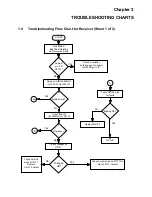
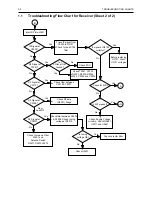
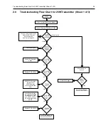
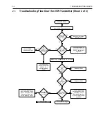
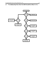
TROUBLESHOOTING CHARTS
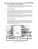
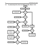
4.0
Troubleshooting Flow Chart for Synthesizer
+5V at
U3201 Pin’s
13 & 30?
5V
at pin 6 of
D3201
Is information
from
µP U0101
correct?
Is U3201
Pin 47
= 13VDC ?
Is U3301 Pin 19
<40 mVDC in RX &
>4.5 VDC in TX?
(at VCO section)
Start
Visual
check of the
Board OK?
Correct
Problem
Check 5V
Regulator
U3211
Is 16.8MHz
Signal at
U3201 Pin
19?
Check
Y3261, Y3263 and
associated Parts
Are signals
at Pin’s 14 &
15 of U3201?
Check
R3201
Check C3319
Is U3201 pin 2
>4.5 VDC in Tx &
<40 mVDC in Rx
Replace
U3201
Remove
Shorts
Is there a short
between Pin 47 and
Pins 14 & 15 of
U3201?
Replace or resolder
necessary components
Is RF level at
U3201 Pin 32
-12 < x <-25
dBm?
Are
R3221,
R3222, R3223,
C3221, C3222,
& C3224
OK?
Replace
U3201
If R3227, C3226 & C3227
are OK, then see VCO
troubleshooting chart
Are Waveforms
at Pins 14 & 15
triangular?
Do Pins
7,8 & 9 of
U3201 toggle
when channel is
changed?
Check programming
lines between U0101
and U3201 Pins 7,8 & 9
Replace
U3201
Check µP U0101
Troubleshooting
Chart
No
Yes
No
Yes
No
Yes
No
No
No
Yes
Yes
No
Yes
Yes
No
Yes
Yes
Yes
No
No
No
No
Yes
No
Yes
Yes
Check D3201,
C3202, C3203,
C3205 & C3206
5V at
U3201 pins 5,
20, 34 & 36
Check 5V
Regulator
U3211, R3211
Is
16.8MHz
signal at
U3201 pin
23?
Replace
U3201
Yes
No
No
Yes
No
Yes


