


3-4
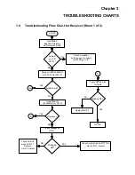
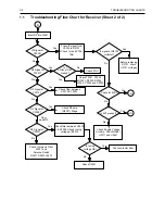
TROUBLESHOOTING CHARTS
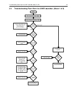
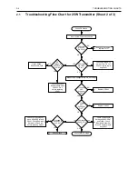
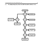
2.1
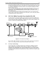
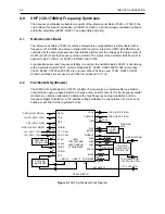
Troubleshooting Flow Chart for 25W Transmitter (Sheet 2 of 3)
Check PA Stages
No or too low Power when keyed
Measure DC Voltage at Pin 2 & 3 of U3401
>6
YES
DC Voltage
at U3501
Pin 23 =0?
2-6
DC Voltage
at U3402-1
Pin 1?
YES
Pin 2 Voltage
0.62 *
Voltage at
Pin 1?
If U3201 Pin 2 is high,
replace PCIC
NO
Replace U3401
YES
NO
DC
Voltage at
U3402-1 Pin
3 = 8.8V?
Check S3440,
R3442 and R3443
YES
Pin 3 Voltage
0.51 *
Voltage at
Pin 1?
NO
Replace U3401
<2V DC Voltage at
U3402-2 Pin
7?
>6V
Check Components
between U3402-2 Pin7
and Q3421. Check
Resistive Network at
Pins 5 & 6 before repla-
cing Q3421
YES
DC Voltage at
U3402-2 Pin
5 <8.8V?
Check Components bet-
ween U3402-2 Pin7 and
Q3421. Check Resistive
Network at Pins 5 & 6
before replacing Q3421
NO
Check Q3422
NO
Check Final PA Stage
2-6V
<2V
Check Resistive Net-
work at Pins 2 & 3 of
U3402-1 before repla-
cing U3401
Check Q3442 and
Resistive Network at
U3402-1 Pin 3
before replacing
U3401


