
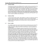


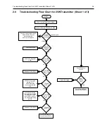
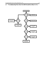


Troubleshooting Flow Chart for 25W Transmitter (Sheet 1 of 3)
3-5
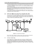
2.2
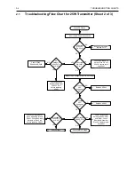
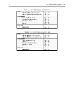
Troubleshooting Flow Chart for 25W Transmitter (Sheet 3 of 3
)
Check Final PA Stage
NO
0V
1-4V
Bias 2 DC
Voltage at
TP3406?
YES
RF Voltage
at TP3401
>100mV?
YES
RF Voltage
U3401 Pin 6
>3V?
Supply
Replace Q3441
Check FGU (U3301)
NO
Check Components
between TP3401 &
C3417
NO
YES
ASFIC
U0221 Pin 6
1-4V DC?
Check Bias Tuning
before replacing ASFIC
U0221
Check Components
between ASFIC and
Q3441 before repla-
cing Q3441
YES
RF Voltage
Q3421 Gate
>1V?
NO
Check Components
between C3417 &
Q3421
YES
RF Voltage
Q3441 Gate
>4V?
NO
Check Components
between Q3421 &
Q3441
Check Components
between Q3441 &
Antenna Connector
Voltage


