Initial Setup
12
G30 Developer’s Kit
December 15, 2009
Connecting External Accessories
Replace the Developer Board cover and connect the following external connectors in the
sequence shown.
Power Supply
Caution:
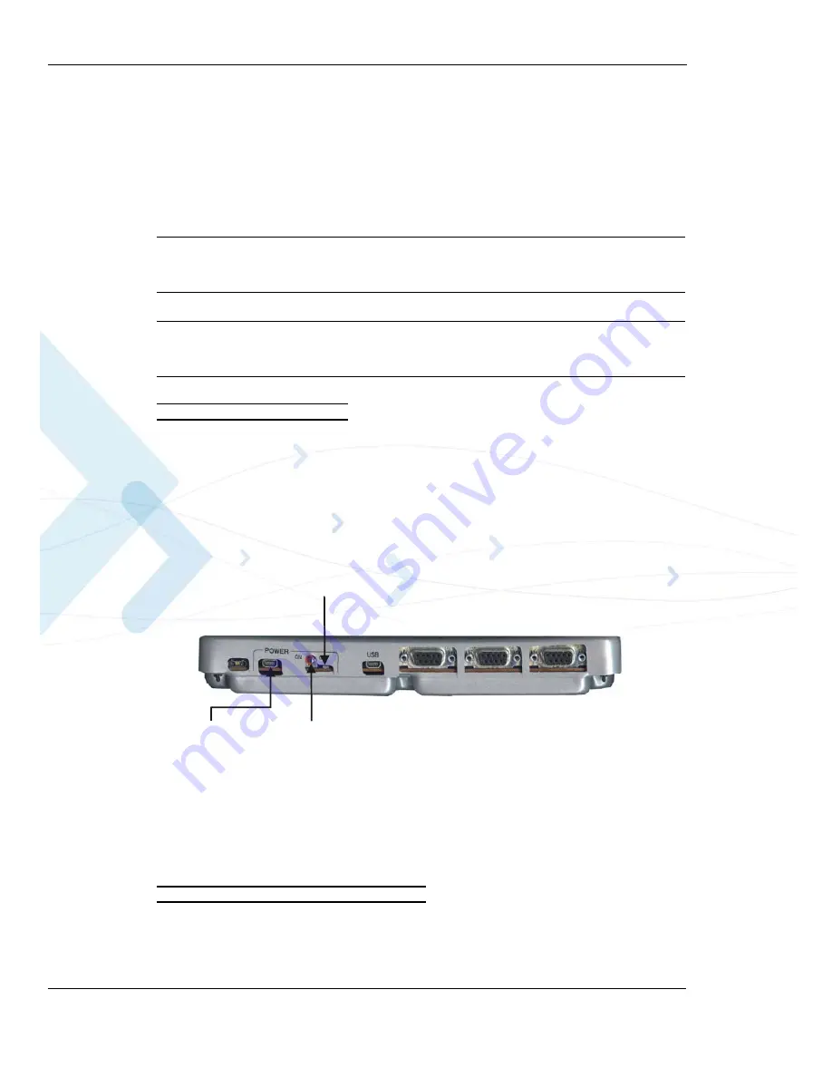
Before connecting the power supply, make sure that the Developer Board On/Off
switch (located in the rear of the board, as shown in
OFF
position.
Caution:
When using the Wall adapter, make sure to insert it into the Power Adapter
Connector (J210) and not to the Mini-AB USB connector (J380), as shown in
To Connect the Power Supply
1. Connect the supplied Wall adapter to the Wall Adapter Connector (J230) (
).
The Wall Adapter Connector is located to the left of the Developer Board On/Off switch
(labeled
Power
) at the rear of the Developer Board.
2. Plug the adapter into a wall outlet.
Note:
The G30 Developer Board can also be powered by an external DC power supply. This
option is described in
.
Figure 2-5: Developer Board Power Switch and Adapter Connector (Rear)
Serial Communications
RS232 serial interface is available for communicating with a PC. The G30 Developer’s Kit
includes the necessary RS232 cable for connecting to a PC.
To Connect Serial Communication Cables
•
) either the supplied RS232 cable with a male D-type connector to
RS232-1 connector (J300), or to the RS232-2 connector (J330) for data logging.
Developer Board
On/Off Switch
Power
Indicator LED
Wall-mount
Adapter Connector


