10-36
DSP56367
MOTOROLA
Enhanced Serial Audio Interface (ESAI)
ESAI Programming Model
10.3.5.4
SAICR Reserved Bits - Bits 3-5, 9-23
These bits are reserved. They read as zero, and they should be written with zero for future
compatibility.
10.3.5.5
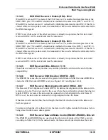
SAICR Synchronous Mode Selection (SYN) - Bit 6
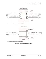
The Synchronous Mode Selection (SYN) bit controls whether the receiver and transmitter
sections of the ESAI operate synchronously or asynchronously with respect to each other (see
Figure 10-11). When SYN is cleared, the asynchronous mode is chosen and independent
clock and frame sync signals are used for the transmit and receive sections. When SYN is set,
the synchronous mode is chosen and the transmit and receive sections use common clock and
frame sync signals.
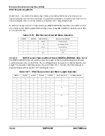
When in the synchronous mode (SYN=1), the transmit and receive sections use the transmitter
section clock generator as the source of the clock and frame sync for both sections. Also, the
receiver clock pins SCKR, FSR and HCKR now operate as I/O flags. See Table 10-7,
Table 10-8 and Table 10-9 for the effects of SYN on the receiver clock pins.
10.3.5.6
SAICR Transmit External Buffer Enable (TEBE) - Bit 7
The Transmitter External Buffer Enable (TEBE) bit controls the function of the FSR pin when
in the synchronous mode. If the ESAI is configured for operation in the synchronous mode
(SYN=1), and TEBE is set while FSR pin is configured as an output (RFSD=1), the FSR pin
functions as the transmitter external buffer enable control, to enable the use of an external
buffers on the transmitter outputs. If TEBE is cleared then the FSR pin functions as the serial
I/O flag 1. See Table 10-8 for a summary of the effects of TEBE on the FSR pin.
10.3.5.7
SAICR Alignment Control (ALC) - Bit 8
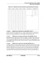
The ESAI is designed for 24-bit fractional data, thus shorter data words are left aligned to the
MSB (bit 23). Some applications use 16-bit fractional data. In those cases, shorter data words
may be left aligned to bit 15. The Alignment Control (ALC) bit supports these applications.
If ALC is set, transmitted and received words are left aligned to bit 15 in the transmit and
receive shift registers. If ALC is cleared, transmitted and received word are left aligned to bit
23 in the transmit and receive shift registers.
Note:
While ALC is set, 20-bit and 24-bit words may not be used, and word length
control should specify 8-, 12- or 16-bit words, otherwise results are unpredictable.
Summary of Contents for DSP56367
Page 16: ...xvi MOTOROLA CONTENTS Paragraph Number Title Page Number ...
Page 22: ...xxii MOTOROLA List of Figures Figure Number Title Page Number ...
Page 26: ...xxvi MOTOROLA List of Tables Table Number Title Page Number ...
Page 148: ...4 6 DSP56367 MOTOROLA Design Considerations PLL Performance Issues ...
Page 248: ...9 30 DSP56367 MOTOROLA Serial Host Interface SHI Programming Considerations ...
Page 306: ...10 58 DSP56367 MOTOROLA Enhanced Serial Audio Interface ESAI ESAI Initialization Examples ...
Page 389: ...Bootstrap ROM Contents MOTOROLA DSP56367 A 15 end ...
Page 390: ...A 16 DSP56367 MOTOROLA Bootstrap ROM Contents ...
Page 432: ...C 8 DSP56367 MOTOROLA JTAG BSDL ...
Page 484: ...D 52 DSP56367 MOTOROLA Programmer s Reference ...
Page 490: ...E 6 DSP56367 MOTOROLA Power Consumption Benchmark ...
Page 516: ...F 26 DSP56367 MOTOROLA IBIS Model ...
Page 522: ...Index 6 MOTOROLA Index ...
Page 523: ......

