7A7
EN
16
17
18
19
20
21
1
6
7
8
9
10
11
12
13
14
15
2
4
K1 K2
16
17
18
19
20
21
1
6
7
8
9
10
11
12
13
14
15
2
3
K1 K2
3
4
1
2
4
3
1
2
3
4
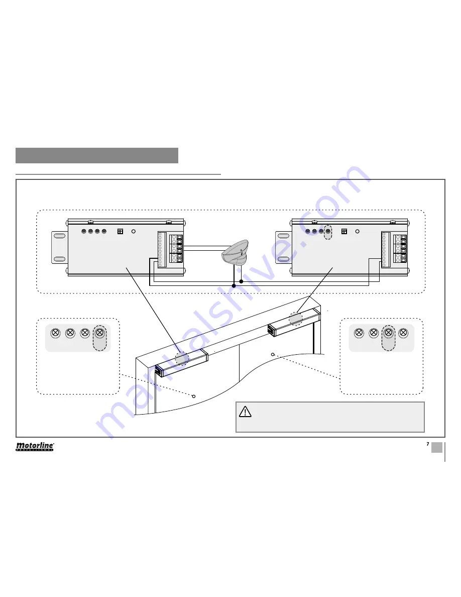
02. CONNECTION SCHEMES
DOOR WITH 2 LEAVES
LEAF Nº1
Set the potentiometer nº3
on the leaf nº1 control board
from to create a delay relati-
ve to the leaf nº2.
LEAF Nº2
Set the potentiometer nº4
on the leaf nº2 control board
from to create a delay relati-
ve to the leaf nº1.
Operation:
When using a door with two leaves, you should note these connections.
This function will allow the two sheets work in a coordinated manner.
All connections must be made with the power supply disconnected.
In this function, if the leaf nº2 encounters an obstacle during closure,
the micro will give opening order to the 2 leaves automatically, for a
correct closure.
Leaf nº2
M1601 Radar
Leaf nº1
Control board 1
Control board 2


