


7.0 REMOTE START
The EP6 features REMOTE START only in AUTO
operating mode.
To operate the REMOTE START, follow the instruc-
tions.
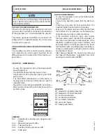
A) - Turn the KEY-SWITCH to the ON position; the
Display and LEDs illuminate for 1 sec.
B) - Wait until the end of the LEDs test.
C) - Push the AUTO pushbutton as soon as possible
(otherwise, after 20 seconds the EP6 enters the
STARTING FAILURE); the [AUTO] yellow LED
will illuminate as described in the section 4.
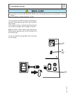
REMOTE START SWITCH:
If the REMOTE START input is activated, the
[AUTO] yellow LED illuminates continuously and the
display will indicate the count down of the internal
start delay
timer. The engine will start after the pro-
grammed
start delay
time. If the REMOTE START
is deactivated, the EP6 drives the
stop delay time
.
The display will indicate the count down and the
[AUTO] yellow LED will flash. The engine will stop
after the programmed
stop delay
time.
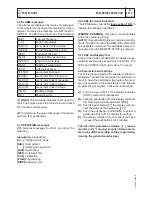
8.0 SAFETY
9.0 Automatic periodic TEST
The EP6 does not use a clock to count the pro-
grammed days ([P.26] setting, section 6.0). The
maximum error and drift of the counter is +/-0,5%.
The user may experiment with shifting the periodic
tests. To avoid error accumulation, and in case your
unit is programmed to allow Automatic Periodic Test,
we recommend the following procedures.
- disconnect the power supply of the EP6
(consult
your genset supplier)
- wait for the desired start time (external clock ref-
erence)
- apply the power supply to the EP6
(consult your
genset supplier)
- select the "AUTO" operating mode
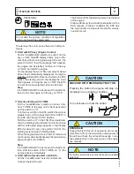
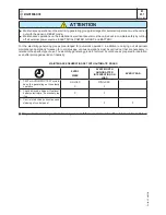
High voltage is present inside the EP6. To avoid
electric-shock hazard, operating personnel must
not remove the protective cover. Do not discon-
nect the grounding connection. Any interruption of
the grounding connection can create an electric
shock hazard. Before making external connec-
tions, always ground the PANEL first by connect-
ing the control panel to ground.
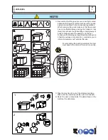
NOTE
!
The EP6 will start the engine after the programmed
number of days and the engine will run for the pro-
grammed time. To determine how the Automatic
Periodic Test is programmed enter the Reading
Mode (section 6.0 parameter [P.26] and [P.27]).
IMPORTANT NOTES
If the supply (battery voltage) is removed, the
EP6 loses the counts and timings. If the sup-
ply restores, the EP6 starts to count the A.P.T.
according to the programmed parameters [P.26]
and [P.27]. It is important to synchronize the
power on sequence with the desired Automatic
Periodic Test.
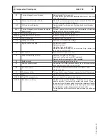
PROTECTIONS
EP6 ENGINE PROTECTION
M
39.12.
4
REV.1-03/11
12/10/05 M39GB
Summary of Contents for GE 20 YSX
Page 27: ...Comandi Controls Commandes Mandos GE 20 YSX M 31...
Page 50: ......


