


USE
WELDING DIGITAL CONTROL
M
33.
2
REV.2-11/12
I
GB
F
TIG MODE
Contact starting TIG
This position is specifically for TIG welding. To cre-
ate the arc simply place the tip of the TIG electrode
on the piece that requires welding then gently move
the tip away. The arc starts automatically and at the
same time the welding current rises to the preset
value, using the welding current adjustment knob
which is on the lower part of the control panel.
The welding current can be adjusted continuously
from a minimum of 10 A to a maximum which depen-
ds on the power of the machine 400 A, 500 A, 600 A.
STICK MODE (Electrode)
Features C.C. (Constant Current)
There are three stick modes which feature increa-
sing “arc forces” so that the arc has different levels
of penetration according to the electrode and/or
welding position.
MIG/MAG MODE (continuous wire)
Features C.V. (Constant Voltage)
All wire type welding processes can be carried out,
naked or coated.
The voltage can be adjusted using the same
knob which adjusts the current in STICK mode.
Adjustment is continuous and goes from a minimum
of 15 V to a maximum of 36V, 40 V.
Optional RC Remote Control
The welding current can also be set from a distance
using the optional remote control. Once the remote
control is connected to the connector (X1), the cur-
rent is controlled by the remote control. To return to
front panel control remove the connector.
Inversion of polarity (Optional, available on
request)
To carry out the inversion of polarity, the action has
given by the switch which is both on the front panel
of the welding control and on the remote control.
By selecting “inversion” the “ON” LED switches off
and the voltage at the welding socket becomes
zero. The power contactor is witched inside the
electrical box and the voltage reappears at the
welding sockets. The “ON” LED switches back on
at the same time.
The “Invert polarity” LED on the front panel near the
welding current adjuster switches on .
You cannot invert polarity in
“MIG/MAG”
mode.
PROTECTIONS
The Welding Digital Control features 3 protections
for the control and chopper.
11/10/04
M33_WDC_GB
1) “ON”
LED blinking
When the engine of the welder is
started the control unit automatically
goes to the stand by mode for few
istants (stand-by LED on) and performs a self-dia-
gnosis of the current sensor connector and power
source v 15V; then the selected process is
loaded (on led turned ON).
In case of malfunction the
“ON” LED
blinks.
2) Red LED blinking
The chopper has a thermal protection,
which intervenes in case the operating
temperature exceeds 85°C.
If the protection intervenes, the red LED begins to
flash and the welding current/voltage goes to zero.
In this case do not switch off the welder, since the
alternator fan will help cool down the chopper more
quickly.
After a few minutes, the LED will automatically
switch itself off and the welding voltage/current will
once again be available at the plugs.
3) Red LED continuously lit
If an anomalous current is detected
in the chopper, the control blocks the
conversion immediately, the output
welding current/voltage goes to zero and the red
LED lights up. To reset everything, it is necessary
to switch off the machine.
If the protections 1) and 3) should intervene, it is
best to immediately contact the nearest authorised
Service Centre.
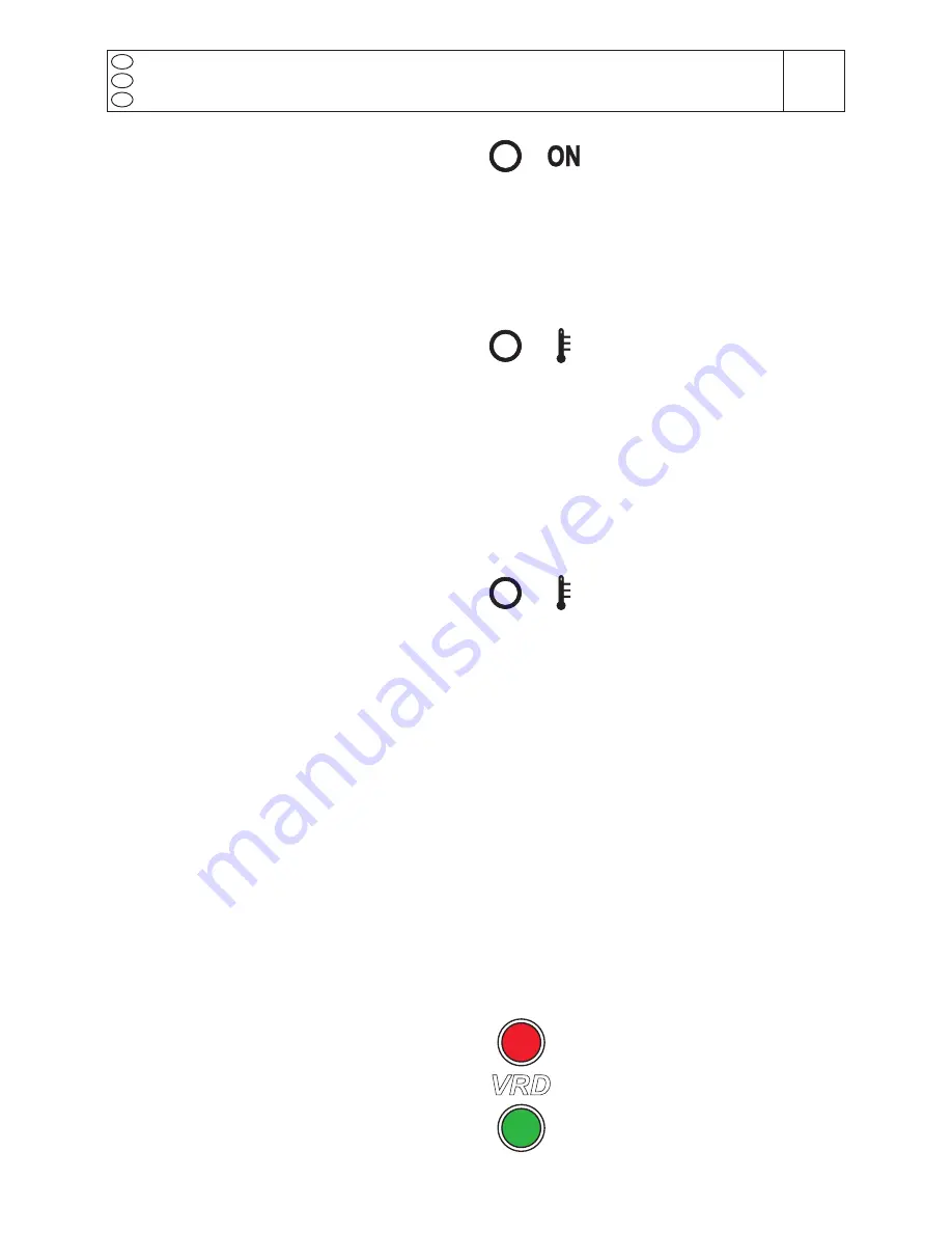
VRD FUNCTION (VRD=Voltage Reduction Device)
The VRD function (present only on some versions)
fulfils the purpose of drastically reducing the harm
which may result to a person from inadvertent con-
tact with the electrode during non-welding pauses.
The VRD automatically switches the control mode
in CV and sets the voltage to a safe value (typically
<13V) each time the welding process is interrupted
for a period longer than 0.5 sec.
The VRD function is active only in CC mode.
The proper operation of the VRD protection (in the
models where it is implemented) is monitored by a
couple of LEDs: one green and one red.
During welding the red LED indicates
that a condition of electrical risk is pre-
sent. When the welding is stopped for
more than 0.5 sec. the green LED turns
on (and the red LED turns off) indica-
ting that the VRD function is active. This
means that the voltage on the electrode
has been lowered to a safe value.
VRD


