
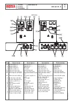


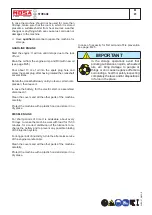


TROUBLE SHOOTING
DSP - EP5/EP7/ES
M
40.3
12/05/05 M40DSP/EP5-ES_GB
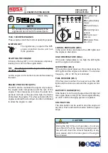
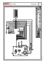
DRAWING 1
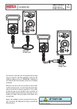
10 Vca
OUTPUT
Check the transformer in this way:
DRAWING 3
OUTPUT 18 Vca
OUTPUT
25 Vca
OUTPUT
18 Vca
input: 220 Vac
output: 18 Vac, 25 Vac, 10 Vac
DRAWING 2
REV.1-02/11
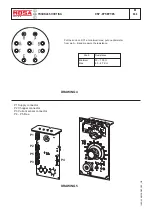
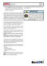
CHOPPER TEST
CHECK THE FOLLOWING RESISTIVE VALUES
ON THE CHOPPER CONNECTOR
Check the resistive values between the following pairs of pins, by
means of an ohmmeter.
WIEW FROM INSERTION SIDE
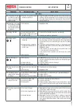
POTENTIOMETER TEST
To check if the potentiometer of the WDC
works correctly perform the following test:
1) Start the welding machine and let it run
at nominal r.p.m.
2) Connect a multimeter set for VDC mea-
surement between pins 1 (GND) and 12
of connector P4
3) Turn the knob completely AKW and check
thet the voltage is
0,5V
4) Turn the knob gradually KW and check
that the voltage increases up to a value
4,5V at rotation stop. the voltage shall
increase in a regular way with the rotation.
Pins
CT 350
DSP 400
DSP 2x400
DSP 500
DSP 600
1 - 9
3,33 K
Ω
± 5% 3,33 K
Ω
± 5% 3,33 K
Ω
± 5%
2 - 10
3,33 K
Ω
± 5% 3,33 K
Ω
± 5% 3,33 K
Ω
± 5%
3 - 11
3,33 K
Ω
± 5% 3,33 K
Ω
± 5% 3,33 K
Ω
± 5%
4 - 12
-
3,33 K
Ω
± 5% 3,33 K
Ω
± 5%
5 - 13
-
-
3,33 K
Ω
± 5%
8 - 16
1,8
÷
25 K
Ω
± 5%
(In funzione della temperatura)
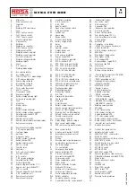
Summary of Contents for DSP 2x400 PS-PL
Page 38: ...DSP 2x400 PSX REV 0 11 05 M 53 Dimensioni Abmessungen Dimension 18 11 05 88412 I...
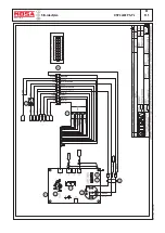
Page 42: ...DSP 2x400 PS PL REV 0 11 05 M 61 2 Stromlaufplan 28 11 05 78413 D...
Page 43: ...DSP 2x400 PS PL REV 1 02 11 M 61 3 Stromlaufplan 28 11 05 78413 D...
Page 44: ...DSP 2x400 PS PL REV 1 02 11 M 61 4 Stromlaufplan 28 11 05 78413 D...
Page 45: ...DSP 2x400 PS PL REV 1 02 11 M 61 5 Stromlaufplan 28 11 05 78413 D...
Page 46: ...DSP 2x400 PS PL REV 1 02 11 M 61 6 Stromlaufplan 28 11 05 78413 D...


