
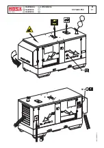


USE AS A GENERATOR
WELDING DIGITAL CONTROL
M
37
REV.1-06/10
09/04/02 M37DSP-GB
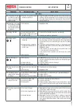
GENERATION IN AC (ALTERNATING CURRENT)
Make certain of the efficiency of the ground connec
-
tion (12). - See page M20 -.
Position the GFI switch to ON.
+
Voltage is now immediately available to the AC
sockets.
Verify that the voltmeter displays the nominal vol
-
tage value (at no load it is close to +10% of the
nominal value).
Connect the electric devices to be powered to the
AC sockets, using suitable plugs and cables in good
condition.
+
Verify that the electrical characteristics (voltage/
frequency/power) of the device being powered
are compatible with those of the generator.
Low frequency and/or voltage can irreparably
damage some electrical devices.
Verify that the ground lead of the electrical applian
-
ce/tool to be powered is correctly connected to the
terminal of the plug.
+
For double insulation devices with the symbol
, the plug’s ground terminal does not need
to be grounded.
THERMAL PROTECTION
The monophase outputs are protected against over
-
loads by the thermal protection (59B).
When the rated current is exceeded, the protection
intervenes to cut off the voltage to the AC socket.
+
Notes:
the intervention of the thermal protection
is not instantaneous, but reacts according
to an overcurrent/time characteristic, whereby the
greater the overcurrent the quicker the intervention.
In case of intervention by the protection device,
verify that the total power for the loads connected
does not exceed the declared rating and decrease
if necessary. Disconnect the loads and wait a few
minutes to allow the thermal
protection to cool down.
Before resetting by pressing
the central button and then
connect the load again.
If the protection should intervene again, replace it
with another one with matching intervention current
specifications and/or contact the Service Depart
-
ment.
. Note: do not forcibly hold the central button of the
thermal protection device to prevent its interven
-
tion, as this could irreparably
damage
the unit’s
alternator.
+
Note: the three phase output does not require any
protection against overcurrents, since it uses a
self-protecting asynchronous type alternator.
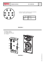
GROUND FAULT INTERRUPTOR SWITCH
The high-sensitivity ground fault interruptor switch
[G.F.I.] (30mA) (D), guarantees protection against
indirect contacts due to faulty ground currents .
When the G.F.I. switch picks up a faulty ground
current that is higher than 30mA, it inter
-
venes by immediately cutting off voltage
to the AC sockets.
In case of intervention by this protection
device, reset the G.F.I. switch by moving
the lever to the ON position. In case of
another intervention, verify that there are no faults
in the tools connected, or replace the G.F.I. switch
with another one of matching specifications and/or
contact the Service Department.
+
Notes:
Verify the operation of the G.F.I. switch
at least once a month by pressing the TEST button.
The generator must be running and the G.F.I. lever
in the ON position.
SIMULTANEOUS USE
The welder’s alternator permits the simultaneous
use of auxiliary power and welding current. The
auxiliary power available to the AC plugs (15) di
-
minishes as the welding current drawn increases.
The table on page M1.6 TECHNICAL SPECIFI
-
CATIONS shows the amount of auxiliary power
available as the welding current varies.
COMBINED USE
The output available from the various auxiliary
power sockets is limited, not only by the declared
output of the unit but also by the capacity of each
individual socket.
PUSH TO
RESET
WARNING
It is strictly forbidden to connect the group to
the public mains and/or to any other source
of electric power.
!
Summary of Contents for DSP 2x400 PS-PL
Page 38: ...DSP 2x400 PSX REV 0 11 05 M 53 Dimensioni Abmessungen Dimension 18 11 05 88412 I...
Page 42: ...DSP 2x400 PS PL REV 0 11 05 M 61 2 Stromlaufplan 28 11 05 78413 D...
Page 43: ...DSP 2x400 PS PL REV 1 02 11 M 61 3 Stromlaufplan 28 11 05 78413 D...
Page 44: ...DSP 2x400 PS PL REV 1 02 11 M 61 4 Stromlaufplan 28 11 05 78413 D...
Page 45: ...DSP 2x400 PS PL REV 1 02 11 M 61 5 Stromlaufplan 28 11 05 78413 D...
Page 46: ...DSP 2x400 PS PL REV 1 02 11 M 61 6 Stromlaufplan 28 11 05 78413 D...


