background image

2-28 

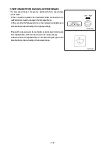
[1] WALK-AROUND CHECK   Applicable to Canopy Specifications 


• Check carefully that there are no dead leaves, waste paper, oil, grease, or other flammable materials around the 

battery or the muffler, or other parts of the engine which reach high temperatures. These flammable materials 
can cause fire.  

• Check carefully that there is no leakage of oil or fuel from the hydraulic hoses or fuel hoses. If any cracks, 

deformation,  or  other  abnormalities  are  found,  repair  them  immediately.  These  problems  will  cause  fire, 
abnormalities in travel, or problems with raising or lowering the dump body.  

• Always use the handrails and steps when getting on or off the machine.  


Before starting the engine at the beginning of the d

ay’s work, look under and around the machine and check the following 

points.  
• Check for dead leaves, waste paper, dust, oil, or grease at places which reach high temperatures.  
• Check for loose or missing bolts, nuts, or connecting pins.  
• Check for leakage of oil, fuel, or coolant.  
• Check for hanging electrical wires or loose connections.  


Applicable to Canopy Specifications


Summary of Contents for MST-800VD

Page 1: ...ne may cause serious injury or death Operators and maintenance personnel must read this manual before operating or maintaining this machine This manual should be kept near the machine for reference and periodically reviewed by all personnel will come into contact with it ...

Page 2: ......

Page 3: ...4 General view of monitor panel 2 5 2 Explanation of components 2 6 2 1 Meters and lamps on control panel box 2 6 2 2 Meters and lamps on monitor panel 2 8 2 3 Switches and levers on control panel box 2 11 2 4 Warning devices 2 13 2 5 Travel lever 2 14 2 6 Dump control lever 2 16 2 7 Dump body safety bar 2 16 2 8 Fuse box in control panel box 2 17 2 9 Fuses and fusible link inside wiring harness 2...

Page 4: ...ump control lever 2 44 4 3 Operating safety bar 2 45 4 4 Precautions during operation 2 46 5 Manual release parking brake 2 47 5 1 Outline of parking brake 2 47 5 2 Method for manual release of parking brake 2 47 6 Handling rubber crawler 2 49 6 1 Features of rubber crawler 2 49 6 2 Prohibited operations for rubber crawler 2 49 6 3 Precautions when using rubber crawler 2 50 7 Transportation 2 51 7...

Page 5: ...d lubricant table 3 6 4 Tools and tightening torques 3 8 4 1 Introduction of necessary tools 3 8 4 2 Torque list for bolts and nuts 3 9 5 Periodic replacement of critical parts 3 10 5 1 Periodic replacement interval every 2 years 3 10 5 2 Periodic inspection 3 10 5 3 Specified periodic replacement parts 3 11 6 Maintenance schedule chart 3 12 7 Service procedure 3 13 7 1 Outline of inspection and m...

Page 6: ...A 4 ...

Page 7: ...0 1 FOREWORD 1 FOREWORD 0 2 2 INTRODUCTION 0 3 3 SAFETY INFORMATION 0 4 4 LOCATION OF SERIAL NUMBER 0 5 ...

Page 8: ...ration and maintenance Some actions involved in operation and maintenance of the machine can cause a serious accident if they are not done in the manner described in this manual Keep this manual handy and have all personnel read it periodically If this manual has been lost or has become dirty and cannot be read request a replacement manual from Morooka or your Morooka distributor If you lend this ...

Page 9: ...performance and shorten the machine life Be sure to break in the machine for the initial 100 hours as indicated by the hourmeter Proper breaking in will allow the machine to give you many years of service During breaking in pay particular attention to the following points After starting the engine idle it for 5 minutes to carry out the warming up operation Avoid operation with heavy loads or at hi...

Page 10: ...ult in serious injury or death if the hazard is not avoided These safety messages or labels usually describe precautions that must be taken to avoid the hazard Failure to avoid this hazard may also result in serious damage to the machine This word is used on safety messages and safety labels for hazards which could result in minor or moderate injury if the hazard is not avoided This word might als...

Page 11: ...urface of the travel lever stand inside the operator s compartment in the position in the diagram on the right For the position of the engine serial number please see the separate engine operation manual When inquiring about service or ordering parts please quote the machine serial number engine serial number and hour meter reading ...

Page 12: ...0 6 ...

Page 13: ...starting engine 1 11 5 Precautions when traveling 1 12 6 Precautions during operation 1 15 7 Precautions for transportation 1 17 8 Position for attaching safety labels 1 18 Read and follow all safety precautions Failure to do so may result in serious injury or death This safety section also contains precautions for optional equipment and attachments ...

Page 14: ... safety lock levers and seat belts properly Improper use of safety features could result in serious bodily injury or death Parking brake switch See OPERATION 3 7 PARKING MACHINE Dump control lever lock See OPERATION 4 2 LOOCKING DUMP CONTROL LEVER Seat belt See OPERATION 2 11 SEAT BELT WEAR SUITABLE CLOTHING Always wear properly fitting clothes which allow ease of movement If there are buttons alw...

Page 15: ...il and fuel in the determined place and do not allow un authorized persons to enter Tighten all fuel and oil caps securely Keep any flame away from flammable fluids Do not leave any cloths or rags soaked in oil or fuel lying in the fuel or oil storage area Clean such materials up immediately Stop the engine and do not bring lighted cigarettes or cigarette lighters close when refueling USE HANDRAIL...

Page 16: ...must be started to carry out inspection or maintenance take steps to ensure that the engine can be stopped at any moment When carrying out the operation with two or more workers determine the order of operation and fix signals and follow the instructions of the person in charge ALWAYS KEEP MACHINE CLEAN Always do the following to keep the machine clean Always keep the floor steps and handrails fre...

Page 17: ...n close to the fan Do not come close to the dump body when it is moving There is danger of getting caught or crushed KEEP AWAY FROM FLAME WHEN ADDING FUEL When filling the fuel tank with fuel or when draining the water always follow the precautions below Stop the engine Do not bring any lighted cigarette or cigarette lighter close to the fuel tank After adding fuel tighten the cap securely and wip...

Page 18: ...oil After adding oil tighten the cap and drain valve securely and wipe up any oil that was spilled WAIT FOR WATER TEMPERATURE TO GO DOWN BEFORE ADDING COOLANT Do not add water to the radiator Always follow the precautions below Stop the engine and wait for the water temperature to go down Raise the lever attached to the radiator cap to release the internal pressure before removing the cap After ad...

Page 19: ...osen the tension adjustment valve more than one turn There is danger that the valve may fly out When adjusting the tension do not stand directly in front of the valve stand to the side to avoid danger USE SAFETY BAR UNDER DUMP BODY When going under the dump body to carry out operations always follow the precautions below Hang a DO NOT OPERATE sign Part No 1 41010 1210 in the operator s compartment...

Page 20: ...nel and control panel switches sensors connectors Starting motor alternator sensors connectors around the engine Battery relay connectors at front right of machine DISPOSE OF WASTE MATERIAL CORRECTLY When draining and changing the oil always put a container under the engine and tank to catch the oil Do not drain the oil directly into the ground or throw it into rivers or the sewage system When dis...

Page 21: ...operator s seat Clean the lights to ensure that they give good visibility Adjust the operator s seat to a suitable position for operation Always adjust the seat if it has been used by another operator Check that the seat belt can be locked properly Always adjust if it has been used by another operator Cab specifications Canopy specifications ALWAYS KEEP OPERATOR S COMPARTMENT CLEAN Always do the f...

Page 22: ...he worksite and determine the best and safest method of operation If there are any dangerous places erect signs and take other steps to ensure safety Check the depth and flow of water and the ground condition before operating in water or crossing a river NEVER be in water which is in excess of the permissible water depth If there are bridges or any other structure check that they are of sufficient...

Page 23: ... Sit properly in the operatorユs seat and fit the seat belt Cab specifications Canopy specifications CHECK FOR SAFETY IN SURROUNDING AREA Always check that there are no people in the surrounding area Be particularly careful to check under the machine Never start the engine if a warning tag has been attached to the controls When starting the engine sound the horn to warn people in the area Do not al...

Page 24: ...cur Do not use the parking brake to stop the machine If a dangerous state occurs by any possibility and when it becomes necessary to stop the machine urgently press the parking brake switch to set it to the STOP position or turn the engine starting switch to the OFF position to stop the engine TRAVEL CAREFULLY ON UNEVEN GROUND OR ON CURVES When traveling on uneven ground or in places where there a...

Page 25: ...ill or slope or parallel to the slope Such action could result in the machine tipping over or slipping When traveling up hills or slopes always travel directly up the slope Set the travel speed to a low range and keep the travel lever close to the N position low speed Do not suddenly change speed on the slope There is danger that the direction of the machine may suddenly change and the machine may...

Page 26: ...y PARKING MACHINE Park the machine on firm level ground Select a place where there is no problem of falling rocks landslides or floods If the machine has to be parked on a slope do as follows Stop the machine facing directly up or down the slope Always put blocks under the tracks to prevent the machine from moving Lower the dump body fully REMOVE KEY WHEN LEAVING MACHINE When leaving the machine a...

Page 27: ...be careful of the following Check that there is no person or obstacle near the dump body Stop the machine at the determined point and operate the dump in accordance with signals from the signalman Block the tracks to prevent the machine from moving in reverse When dumping on slopes there is danger of the machine tipping over If it is felt that there is danger to the machine stop the operation imme...

Page 28: ...the dump body should touch the electric cable the operator should not leave the operator s compartment He should call another worker to report the situation The following actions are effective in preventing accidents 1 Wear shoes with rubber soles 2 Use a signalman to give warning if the machine approaches too close to the electric cables When carrying out operations near high voltage cables do no...

Page 29: ...ows Perform loading and unloading on firm level ground only Stop the engine of the haulage truck apply the parking brake securely then block the tires Set the ramps parallel and in line with the width of the crawlers Fix the hooks of the ramps securely to the truck platform Set the machine to be loaded in line with the ramps then approach the ramps at low speed Do not correct the direction of trav...

Page 30: ...LS Always keep these labels clean If they are lost or damaged always attach them again or replace them with a new label There are other labels in addition to the safety labels listed as follows so handle them in the same way CAB SPECIFICATIONS ...

Page 31: ... Always keep these labels clean If they are lost or damaged always attach them again or replace them with a new label There are other labels in addition to the safety labels listed as follows so handle them in the same way CANOPY SPECIFICATIONS ...

Page 32: ...ecautions when travelling downhill 1 41010 1290 3 Precaution for starting engine and leaving 4 Caution for periodic replacement parts 1 41010 1320 1 12020 1210 5 Precautions for warming up operation 6 Precautions when fitting seat belt 1 41010 1230 1 41010 1310 ...

Page 33: ...r oil inside hydraulic tank 10 Beware of rotating fan and pulley 1 41010 1250 1 41010 1260 11 Beware of high temperature coolant 12 Beware of rotating crawler 1 41010 1240 1 41010 1300 13 Precautions for crawler adjustment valve 14 Warning tag to prevent operation during maintenance 1 41010 1270 1 41010 1210 ...

Page 34: ...1 22 ...

Page 35: ...onofcomponents 2 6 3 Operation 2 26 4 Handlingdumpbody 2 44 5 Manualreleaseofparkingbrake 2 47 6 Handlingrubbercrawler 2 49 7 Transportation 2 51 8 Coldweatheroperation 2 52 9 Long termstorage 2 54 10 Handlingbattery 2 55 11 Troubleshooting 2 58 ...

Page 36: ...ions 1 Battery box 2 Rear view mirror 3 Fuel tank 4 Hydraulic tank 5 Cab 6 Operator s seat 7 Dump body 8 Safety bar 9 Rear idler 10 Carrier roller 11 Track roller 12 Dump control lever 13 Travel motor sprocket 14 Rubber crawler 15 Turn signal lamp 16 Head lamp ...

Page 37: ...ox 2 Rear view mirror 3 Fuel tank 4 Hydraulic tank 5 Canopy 6 Operator s seat 7 Dump body 8 Safety bar 9 Rear idler 10 Air cleaner 11 Carrier roller 12 Track roller 13 Dump control lever 14 Travel motor sprocket 15 Rubber crawler 16 Turn signal lamp 17 Head lamp 18 Travel lever ...

Page 38: ...1 2 GENERAL VIEWOFOPERATOR S COMPARTMENT CabSpecifications 1 Travellever 2 Controlbox 3 Operator sseat 4 Dumpcontrollever CanopySpecifications 1 Travellever 2 Controlbox 3 Operator sseat 4 Dumpcontrollever ...

Page 39: ...cover 10 Slopecautionlamp 11 Tachometer 12 Hourmeter 13 Parkingbrakeswitch 14 Starterswitch 15 Preheatingindicatorlamp 16 Turnsignalpilotlamp Left 1 4 GENERAL VIEWOFMONITORPANEL 1 Enginewatertemperaturegauge 2 Batterychargelamp 3 Engineoilpressurecautionlamp 4 HSToiltemperaturecautionlamp 5 HSToilpressurecautionlamp 6 Fuelgauge 7 Over rundangerlamp 8 Over runcautionlamp 9 Parkingbrakepilotlamp 10 ...

Page 40: ... themachineisnotmoving Use the hourmeter reading as the standard for periodic inspection and maintenance When you stop the engine always turn the starting switch to the OFF position 3 SLOPECAUTIONLAMP Ifthislamplightsupwhentravelingdownhill themachinehasexceededthepermissiblerangeoftheslopeangle Topreventthedangerofoverrun carryoutthefollowingoperationsquicklyandcontinuetotraveldownhill 1 Returnth...

Page 41: ...alswitchinthecombinationswitch When the turn signal switch is turned to LEFT side the left side turn signal lampandpilotlampflashes When the turn signal switch is turned to RIGHT side the right side turn signal lampandpilotlampflashes 6 HEADLAMPHIGHBEAMPILOTLAMP Thisshowstheoperationofthelightswitchinthecombinationswitch WhenthelightswitchisturnedtoHIBEAM thehighbeampilotlamplightsup 7 ROOMLAMP WI...

Page 42: ...eachday 3 PARKINGBRAKELAMP Thisshowstheoperationoftheparkingbrake IftheparkingbrakeswitchissettotheON STOP positionwhentheengineis running thelamplightsup IftheparkingbrakeswitchissettotheOFF RUN positionwhentheengineis running thelampgoesout 4 HIGH SPEEDTRAVELPILOTLAMP Thislightsuptoinformtheoperatorthatthemachineisinthehighspeedtravel range When the Hi Lo speed range selector switch is set to th...

Page 43: ...ingunloadedonflatground butthisdoesnotindicateanyabnormality When the machine is traveling on a slope this warns the operator that the machineisinanextremelydangeroussituation ThemonitorlightsupiftheengineandHST mainpump travelmotor exceed thenormalmaximumenginespeedwhentravelingdownhill 8 OVERRUNDANGERLAMP Ifthislamplightsupwhentravelingdownhill itmeansthatthemachineisinanextremelydangeroussituat...

Page 44: ...there is no abnormality please contact your distributor 10 HSTOILTEMPERATURELAMP ThiswarnsofanabnormalityintheHSThydraulicoiltemperature Thislampshouldbeoutduringoperations If itlightsupduringoperations theHSThydraulicoil temperaturehasdropped below20 orhasrisentoapprox 95 If the HST hydraulic oil temperature is below 20 carry out the warming up operationuntilthemonitorgoesout If the HST hydraulic...

Page 45: ...roperly there is danger that the service life of the engine partswillbereduced Neverstoptheenginesuddenlyexceptincasesofemergency If theenginehasoverheated donot suddenlystop it Run the engineat amidrangespeedandgraduallycool it downbeforestoppingit Thisleverisusedtocontroltheenginespeedandoutput Pulledback Enginerunsathighspeed Pushedforward Enginerunsatlowspeed 3 HI LOSPEEDRANGESELECTORSWITCH Wh...

Page 46: ...s clockwise Head lamp Hi and instrument lightinglightup Move lever back Left turn signal lamp and turn signal pilot lamp on control panelboxflashes Move lever forward Right turn signal lamp and turn signal pilot lamp on controlpanelboxflashes 6 HEATERSWITCH ApplicabletoCabSpecifications If the heating is used continuously for a long time the quality of the air inside the operator s compartment wil...

Page 47: ...ill do as follows to prevent any danger from overrunning 1 Operatethethrottlelevertosettheenginespeedtolowspeed 2 Setthetravelleveras close as possible to the N position thendrivethe machinecarefully 3 If the load in the dump body exceeds the maximum payload or is near the maximumpayload reducetheload 3 BACKUPBUZZER Backupbuzzer 3 isinstalledontheleftsideinsidetheframeattherearofthechassis Whenthe...

Page 48: ...WARDorREVERSE andbecomelighteras theyareoperatedbacktowardsN neutral 1 TRAVELINGSTRAIGHTORSTOPPING Operatetheleftandrighttravelleversatthesametime FORWARD Pushtheleversforward REVERSE Pulltheleversback STOP ReturntheleverstotheNposition 2 TURNING STEERING Operate the left and right travel levers at the same time but operateone lever morethantheother Traveling forward and turning left Push the righ...

Page 49: ...ndoperatetheothertravellever inthedirectionofFORWARDorREVERSE Spinturn counterrotationturn Operatetheleftandrighttravelleversinoppositedirections 5 CHANGINGTRAVELSPEED Changetheangleofthetravellevertochangethespeed Operatethetravelleverasmallamounttotravelatlowspeed andoperateita largeamounttotravelathighspeed ...

Page 50: ...umpbody Therearethreeoperatingpositions RAISE HOLD andLOWER RAISE Thedumpbodyisraised HOLD Thedumpbodyisstoppedandheldinposition LOWER Thedumpbodyislowered When the control lever is released it automatically returns to the HOLD position 2 DUMPCONTROLLEVERLOCK Leverlock 2 isusedtoholdthedumpcontrolleverattheHOLDposition 2 7 DUMP BODY SAFETY BAR Ifitisnecessarytogounderthedumpbodytocarryoutinspectio...

Page 51: ...aceit 1 Remove 4 bolts 1 under side of the control panel box and remove inspectioncover 2 2 Removefuseboxcover 3 andcheckorreplacethefusesinsideit 3 Thefusesinsidethefuseboxareforthecircuitsshowninthetablebelow No Capacity Nameofcircuit 1 3A Hourmeter monitorlamps 2 15A 3 15A Combination switch flasher relay head right relay hornrelay 4 10A Wiperswitch 5 10A Cabpowersource 6 15A Parking brake swit...

Page 52: ...e 3 20A Fuse 4 5A If the engine does not start even when the starting switch is turned to the STARTposition carryoutinspectionandreplacement Whenthisisdone theenginewillnotstartiftheparkingbrakeswitchisattheOFF RUN position Alwaysturntheparking brakeswitchtotheON STOP positionbeforecarryingoutoperations 2 METHODOFREPLACEMENT Replacethesefusesandfusiblelinksasfollows 1 Openthebatteryinspectioncover...

Page 53: ... in the seat use suspension adjustment lever 1 at the seat right back side toadjustthesuspension 1 Sitintheseat makesurethatindicator A inred attheleftsideof theseat alignswithredline B ontheframe That indicator A aligns with red line B brings the most comfortable hardnessoftheseat The position of indicator A changes according to the weight of an operator on the seat A lighter weight can move the ...

Page 54: ... atthelowerfrontsideoftheseatand seat rear height adjustment lever 6 at the rear right side to adjust the seat height Donotsitintheseatduringadjustment Adjustment of seat front height Guideatthefront 5 canbeadjustedinfourlevels 1 Holdlever 4 andthefrontsideoftheseattogether andpulllever 4 up 2 While holding lever 4 hold the front side of the seat surface and set guide 5 toadesiredposition 3 Take y...

Page 55: ...forwardorbackwardtoset ittoadesiredposition 2 Takeyourhandofflever 1 andpresstheseatslightlytolocktheseat 2 ADJUSTMENTOFRECLININGANGLE Sit in the seat use reclining adjustment lever 2 at the seat left back side to adjusttherecliningangle 1 While pulling lever 2 up sit up straight to move your back away from the backrest Thebackresttiltsforward 2 While pulling lever 2 up press your back against the...

Page 56: ...on where it is possible to operate the travel lever easily For details see 2 10 OPERATOR S SEAT in the operationsection 2 Hold seat belt buckle 1 and tongue 2 in your left and right hands and inserttongue 2 intobuckle 1 3 Pulltheseatbelttocheckthatthetongueandbucklearelockedsecurely 4 When removing the seat belt press the center of buckle 1 and pull out tongue 2 2 ADJUSTINGSEATBELTLENGTH Adjust th...

Page 57: ...indow lowerthefrontwindowslowlyandbecarefulnottogetyourfingerscaught Afterclosingthefrontwindow alwayssetthelocklevertotheLOCKposition 1 METHODOFOPENINGFRONTWINDOW 1 Hold left and right lock levers 2 of the front window 1 and push down to FREEposition 2 Hold left and right grips 3 and then pull front window 1 up slowly and pushittotherear Frontwindow 1 isstoredinsidetheroof 2 METHODOFCLOSINGFRONTW...

Page 58: ...heinspectioncover 1 Release 2 catches 2 at the front and rear of inspection cover 1 then pull catches 2 up Thecoverisheldintheopenpositionbythedamper 2 Aftercompletion of inspection andmaintenance grip front and rear catches 2 oftheinspectioncover 1 andreturnittotheframe thenfitfrontandrear catches 2 2 16 FRONTGRILL When cleaning the radiatorfins oil coolerfinsor inter coolerfins do asfollows tore...

Page 59: ...ween the jack and the undercover to prevent damagetotheundercover 2 Remove3mountingbolts 2 thenlowerthejackandopenundercover 1 3 After completion of inspection and maintenance put undercover 1 on the jack set it at the mounting position under the machine then tighten mountingbolts 2 ApplicabletoCabSpecifications ApplicabletoCanopySpecifications ...

Page 60: ...ses If any cracks deformation or other abnormalities are found repair them immediately These problems will cause fire abnormalitiesintravel orproblemswithraisingorloweringthedumpbody Alwaysusethehandrailsandstepswhengettingonoroffthemachine Before starting the engine at the beginning of the day s work look under and around the machine and check the following points Checkfordeadleaves wastepaper du...

Page 61: ...er sprocket idler Check for any wear breaks or cracks Check for any loose or missing nuts or bolts Tighten if necessary and repair any abnormalities 4 Checkundermachine Checkthehydraulictankandfueltankforleakage andcheckthegroundunderthemachinefortracesofoil fuel orcoolant If anysignsofleakagearefound checkforthesourceoftheleakageandrepairanyabnormality Checkforlooseormissingnutsandboltsfromtheund...

Page 62: ...rmation or other abnormalities are found repair them immediately These problems will cause fire abnormalitiesintravel orproblemswithraisingorloweringthedumpbody Alwaysusethehandrailsandstepswhengettingonoroffthemachine Before starting the engine at the beginning of the day s work look under and around the machine and check the following points Checkfordeadleaves wastepaper dust oil orgreaseatplace...

Page 63: ...er sprocket idler Check for any wear breaks or cracks Check for any loose or missing nuts or bolts Tighten if necessary and repair any abnormalities 4 Checkundermachine Checkthehydraulictankandfueltankforleakage andcheckthegroundunderthemachinefortracesofoil fuel orcoolant If anysignsofleakagearefound checkforthesourceoftheleakageandrepairanyabnormality Checkforlooseormissingnutsandboltsfromtheund...

Page 64: ...arting 1 Check addcoolant 2 Check addfuel 3 Checkenginelubricatingoillevel addoil 4 Check addoiltohydraulictank 5 Checkdustindicator 6 Check adjustfanbelttension 7 Checkelectricalwiring 8 Checkoperationofswitches lamps gauges 9 Checkoperationofhorn alarmbuzzer 3 ADJUSTOPERATOR SSEAT Adjusttheoperator sseatbeforeoperations Alwaysadjusttheoperator sseatafterithasbeenusedbyanother operator Adjusttheo...

Page 65: ...attheleftandrighttravelleversareattheNposition 2 CheckthattheparkingbrakeswitchisattheON STOP position 3 Check that the dump body is completely lowered and that dump control lever 1 isattheHOLDposition 4 Checkthatlocklever 2 ofthedumpcontrolleverisattheLOCKposition ...

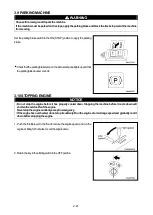
Page 66: ... without setting the parking brake switchtothisON STOP position Do not crank the starting motor continuously for more than 15 seconds If the engine does not start wait for at least 2 minutes before trying tostartagain 1 NORMALSTARTINGENGINE 1 Pullthethrottleleverbackandsetittothelowspeedposition 2 Insertthekeyinthestartingswitch andturnittotheSTARTposition 3 Aftertheenginestarts releasethekey Thek...

Page 67: ...rnittothePREHEATpositionandhold itinpositionuntilthepreheatingindicatorlamponthecontrolpanelboxlights up Thepreheatingtimeisapprox 8seconds Whenthekeyisreleased itwillreturnautomaticallytotheOFFposition 3 When the resistor on the instrument panel glows red turn the key to the STARTpositionandstarttheengine 4 Aftertheenginestarts releasethekey ThekeywillreturnautomaticallytotheONposition ...

Page 68: ...erate dump control lever 1 to theRAISE position raise the dump body to the maximum height and run the engine in this condition for approx 5 minutes Keepdumpcontrollever 1 attheRAISEposition 4 Keep dump control lever 1 at the RAISE position turn the engine throttle levertotheright clockwise furthertoruntheengineathighspeed andrun theengineinthisconditionfor2 5minutes This operation warms up the hyd...

Page 69: ... angle of the slope goes above a certain range the SLOPE CAUTION lamp on the instrument panel lights up and the slope alarm buzzer at the rear of the operator s compartment soundstowarntheoperator Itisdangeroustostartthemachineoffwiththedumpbodyloadediftheslopealarmbuzzersounds Reducetheenginetolowspeed setthetravelleverclosetotheNposition andstartthemachineoffcarefully 1 Pullthethrottleleverbacka...

Page 70: ...theenginetolowspeed setthetravelleverclosetotheNposition andstartthemachineoffcarefully If a dangerous state occurs by any possibility and when it becomes necessary to stop the machine urgently press the parking brake switch to set it to the ON STOP position or turn the engine starting switch to the OFF positiontostoptheengine WhenswitchingbetweenFORWARDandREVERSE alwaysstopthemachinebeforeshiftin...

Page 71: ...achinechangestothehighspeedrange At the same time the high speed lamp on the instrument panel lights up to showthatthemachineistravelinginthehighspeedrange If the switch is pressed again the mechanism inside the travel motor returns toitsoriginalposition andthemachinetravelsinthelowspeedrange At the same time the high speed lamp on the instrument panel goes out to showthatthemachineistravelinginth...

Page 72: ...g brake switch to set it to the ON STOP position or turn the engine starting switch to the OFF positiontostoptheengine 1 GRADUALTURN Theradiusoftheturnisdeterminedbythedifferenceintheamountthattheleft and right travel levers are operated The larger the difference between the left andrighttravellevers thesmallertheradiusoftheturnwillbe Turningwhileincreasingspeed Tomakeagradual turnwhentravelingfor...

Page 73: ...heleft pushthelefttravelleverbacktowardsSTOP Whenturningtotheright pushtherighttravelleverbacktoward 2 PIVOTTURN OperatethetravelleverononesideandsettheotherleverattheNposition Only the crawler on the side that is operated will rotate so the machine will makeapivotturn Toturntotheleftwhentravelingforward pushtherighttravelleverforward Toturntotherightwhentravelingforward pushthelefttravelleverforw...

Page 74: ...IfthetravelleverismovedpasttheNposition it willcausefailuressuchasreverserotationoftheengine ReturntheleftandrighttravelleverstotheNposition Thehydraulicbrakeisautomaticallyappliedandthemachinewillstop 3 8 EMERGENCY STOPPINGMACHINE If a dangerous state occurs by any possibility and when it becomes necessary to stop the machine urgently press the parking brake switch to set it to the ON STOP positi...

Page 75: ...gbrakebuzzersounds 3 10 STOPPING ENGINE NOTICE Do not stop the engine before it has properly cooled down Stopping the machine before it cools down will shortentheservicelifeoftheengine Neverstoptheenginesuddenlyexceptinemergency Iftheenginehasoverheated donotstopitsuddenly Runtheengineatamid rangespeedandgraduallycoolit downbeforestoppingtheengine 1 Push the throttle lever to the front to reduce t...

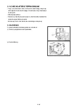
Page 76: ...l and water If any abnormality is found repairit Fillthefueltankwithfuel Remove any dead leaves waste paper or other flammable materials from aroundtheenginethatmaycausefire Removeanymudorsnowstucktotheundercarriageordumpbody 3 12 LOCKING Topreventvandalism thefollowinglocationscanbelocked 1 Cabdoor ApplicabletoCabSpecifications 2 Fueltankfillercap ...

Page 77: ... SLOPE CAUTION lamp on the control panel box lights up and the slope alarm buzzer under the operator s seat sounds to warn the operator It is dangerous to travel with the dump body loaded if the angle alarm buzzer sounds Reduce the engine to low speed set the travel lever close to the N position and drive the machine carefully 4 PRECAUTIONSWHENENGINESTOPSONSLOPES Iftheenginestopsonaslope doasfollo...

Page 78: ... the dump control lever is released it automatically returns to the HOLDposition 1 Stopthemachinecompletely Fordetails see 3 7STOPPINGMACHINE 2 Pullthethrottleleverbackandraisetheenginespeedsufficiently 3 Pullthedumpcontrollever 1 up Thedumpbodywillrise When the dump body comes near to the max height push the dump controlleverdowntoreducethespeedofthedumpbody 4 Pushthedumpcontrollever 1 down Thedu...

Page 79: ...rstarttheengineandoperate thedumpcontrol lever to theLOWER position Ifthisisdone thesafetybarwillhitthedumpbodyandmaybreak 1 INSTALLINGSAFETYBAR 1 Raise the dump body to at least 45 degrees For details see 4 1 OPERATINGDUMPBODY 2 Raisesafetybar 1 andsetitinholder 2 inthebottomsurfaceofthedump body 3 Stoptheengineandpushthedumpcontrolleverdown Thedumpbodywill godownunderitsownweight If thedumpbodyd...

Page 80: ...s Thesignalmanmustalwayscheckthesafetyofthedumpingpointcarefully 2 PRECAUTIONSFORLOAD Donotoverloadthemachine Donotfitsideracksorplates ormakeothermodificationstoextendthesizeofthedumpbodytoincreasetheload Whenloadingthedumpbody alwaysspreadtheloaduniformly Loadingthedumpbodyunevenlywillcauseinstabilityandmaycausethemachinetotipover Becarefulnottolettheloadingbucketorcranehookhitthedumpbodyorflaps...

Page 81: ...when removing plugs and hoses do not stand directlyinfrontofthem loosenthemgraduallybeforeremoving Whenthehosesareremoved alargequantityofoilwillcomeout soalwayscatchtheoilinanoilcontainer When releasing the parking brake manually the operation involves dangerous work such as removing high pressurehoses soalwayspaycarefulattentiontosafetyduringtheoperationandcontactyourdistributor beforestartingth...

Page 82: ...arryoutthefollowingpreparatorywork Go under the machine and turn adjustment screw 7 of multi function valves 6 4places atthebottomofmainpump 5 approx 3 5turnstotheleft TheoilinsidetheHSTcircuitwillflowfreely When starting normal operations again after completion of repair of the machine alwaysturnadjustmentscrew 7 ofmulti functionvalve 6 approx 3 5turnstotherighttoreturnittotheoriginalposition Ift...

Page 83: ...hard rocky ground extremely roughrockbed inplaceswithmanytreestumps onsteelrodsorsteelscrap or places with many sharp objects or on concrete surfaces will cause damagetotherubbershoe On riverbeds or other jobsites where there are large numbers of rocks of different sizes the rocks will get caught in the rubber shoe and damage the shoeorcauseittocomeofftheroller Donotletoil fuel orchemicalsolventge...

Page 84: ...as possible avoid handling loads that produce oil when crushed soy beans corn vegetables etc If the machine is used for handling such products besuretowashthetrackthoroughlyafteruse Whenhandlingloadssuchassalt ammonium sulphate potassiumchloride potassium sulphate or phosphates be sure to wash the track thoroughly afteruse On snow or frozen road surfaces the rubber shoe will slip very easily Be ca...

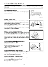
Page 85: ...s anddriveupordowntherampsslowlyto theloadorunloadthemachine 4 To prevent the machine from moving during transportation put wooden blocks under the front and rear of the rubber crawler and secure the machinewithchainsorwirerope Beparticularlycarefultosecureitsothatitcannotsliptotheside 7 2 PRECAUTIONSFOR LOADING When loading and unloading the machine park the trailer on a flat firm roadbed Keep a ...

Page 86: ...eoverheating rust corrosionorfreezinginthecoolingsystem useamixtureoflonglifecoolantwithtapwater forenginecoolingwater Thecoolantservesanti rust anti corrosion andantifreeze Itshouldbeusedyeararound Thecoolantmixtureratiomustbe30 orhighertoensureanti rustandanti corrosionproperties COOLANTMIXTURERATIO Use the following table as a guide The table shows examples when the amount of cooling water is 1...

Page 87: ... Mudandwateronthemachinebodyshouldbecompletelyremoved Thisistopreventdamagetotheseal causedbymud ordirtgettinginsidethesealwithfrozendropsofwater Parkthemachineonconcreteorhardground Ifthisisimpossible parkthemachineonwoodenboards Openthedrainvalveanddrainanywatercollectedinthefuelsystemtopreventitfromfreezing As the battery capacity drops markedly in low temperatures cover the battery or remove i...

Page 88: ...peration must be carried out inside a building open the windows and doors to ensure good ventilationandpreventgaspoisoning Whenthemachineisinlong termstorage starttheengineonceamonthandcarryoutthewarming upoperationthoroughly Inaddition movethemachineforashortdistance andcarryouttheraiseandloweroperationthoroughlyforthedumpbody Ifthecoolingwaterhasbeendrainedfromthemachine alwaysfillwithcoolingwat...

Page 89: ... sparks Do not carry tools inyourbreastpocket Defective contact caused by loose battery terminals can generate sparksandleadtoanexplosion Tightenthebatteryterminalssecurely 10 1 PRECAUTIONS WHEN HANDLING BATTERY Alwaysbecarefulnottoletthebatterybecomedischarged Do not wait for the battery to become discharged before recharging it measure the specific gravity of the battery electrolyte beforehandan...

Page 90: ...argethebatterywhenitisstillmountedonthemachine doasfollows It is dangerous if the temperature of the battery electrolyte exceeds 45 during charging so stop charging and waitforthetemperaturetogodown Disconnectthewiringfromthebatteryterminalsbeforecharging Thereisdangerofabnormalvoltagebeingappliedtothealternatoranddamagingit When disconnecting the wiring always disconnect the negative terminal wir...

Page 91: ...uld be suitable for the battery capacity Check that they are not corrodedordamaged Thebatteryonthenormalmachinemustbethesamecapacityasthatontheproblemmachine 1 CONNECTINGTHEBOOSTERCABLES The numbers in the diagram on the right show the order for connectingthecables 1 Make sure that the starting switches of the normal machine and problemmachinearebothattheOFFposition 2 Connect the clips at the ends...

Page 92: ... Contactyourdistributor After warming up operation Engine oil pressure lamp on instrument panel stays lighted up even when engine speed is raised Engineoilpressuredoesnotrise Lackofengineoil Cloggedengineoilfilter Failureinengineparts Check addoil Replacenewparts Contactyourdistributor Engine water temperature gauge points to around red range or steam spurts out fromnearradiatorsystem Lackofcoolan...

Page 93: ...urdistributor HSToilpressurelamponinstrumentpanel lightsupduringoperation HSToilpressureislowered Cloggedhydrauliclinefilter Clogged strainer inside hydraulic tank Defectivewiring Failureinhydraulicequipment Check clean Check clean Check repair Contactyourdistributor Abnormal noise generated from around pump Clogged strainer inside hydraulic tank Leakageofoilfromhydraulicsystem Failureinhydraulice...

Page 94: ...o notlightup Blownbulb Defectivewiring Replace Check repair Horndoesnotsound Blownfuse Defectivewiring Defectivehorn Check replace Check repair Check replace Left rightturnsignallampsdonotflash Blownfuse Defectivewiring Defectiveflasherrelay Defectiveflasherswitch Check replace Check repair Check replace Check replace Parkingbrakebuzzerdoesnotsound Blownfuse Defectivewiring Defectivebuzzer Defecti...

Page 95: ...aintenance 3 2 2 Precautionsformaintenance 3 4 3 Useoffuelandlubricantsaccordingtoambienttemperature 3 6 4 Toolsandtighteningtorques 3 8 5 Periodicreplacementofcriticalparts 3 10 6 Maintenanceschedulechart 3 12 7 Serviceprocedure 3 13 ...

Page 96: ...urities get into the fuel always store the fuel indoors and carry out refueling operations in a dust free environment If fuel isstoredindrum cans storethedrum cansontheirsidessothattheportsinthedrum cansareinastraightline tothe side Thisactionwillpreventdampairfrombeingsuckedin Topreventmoistureintheairfromgettingintothefueltank alwaysfillthetankafterthecompletionofeachday swork Ifthemachinerunsou...

Page 97: ...em Alwayscontactyourdistributorbeforeinstallingadditionalelectricalequipmenttoyourmachine Afterthemachinehasbeenusedneartheseaorafterithasbeenusedforspreadingfertilizer wipetheelectricalcomponents carefullywithadryclothtopreventcorrosion 7 HYDRAULICSYSTEM The hydraulic equipment is at high temperature and high pressure during operations andimmediatelyafter operations have beencompleted Whencarryin...

Page 98: ...ulictank HydraulicoilISOVG46 IdemitsuKosanSuperHydroX46 Travelmotorreductiongearcase SAE90GL 5 ShinNihonSekiyuGearLubeSP90 4 PRECAUTIONSWHENWASHINGORCLEANINGMACHINE 1 Wash or clean the machine to make it easier to locate problem points In particular wash the oil filler level gauge and greasingplugstopreventdirtormudfromenteringwhenaddingoilorgrease 2 Coverelectricalparts suchasthestartingmotororal...

Page 99: ...emountingsurfaceandalwaysreplacethe sealwithanewpart 11 PRECAUTIONS WHEN CARRYING OUT INSPECTION AND MAINTENANCE OF A MACHINE AFTER OPERATIONSINDUSTYAREAS Checkcarefullyforcloggingoftheaircleaner andcleantheaircleanerelementmorefrequently Cleantheradiatorcore oilcoolercoreandintercoolercoremorefrequentlytopreventclogging Replacethefuelfiltermorefrequently Cleanelectricalpartscarefully inparticular...

Page 100: ...agents Otherwise the fuel injectionsystemmaybedamaged Neverusekerosene asitmaycauseatrouble Selectthefuelandoilfromthetablebelowaccordingtotheambienttemperature Thespecifiedcapacityisthetotalamountofoil includingtheoilinthepipingofthevariouscomponents Therefillcapacityistheamountofoiladdedwhenchangingtheoilduringinspectionandmaintenance When starting the engine in an ambient temperature of lower t...

Page 101: ...tionCDasengineoilandifAPIclassificationCC reducetheengineoilchangeintervaltohalf Thereisnoproblemifsinglegrade oilismixedwithmultigradeoil SAE10W 30 15W 40 butbesuretoaddsinglegradeoil thatmatchesthetemperatureinthetable We recommend genuine oil which has been specifically formulated and approved for use in engine and hydraulic work equipmentapplications Specifiedcapacity Totalamountofoilincluding...

Page 102: ... pleaseordernewtoolsfromyourdistributor No Nameoftool PartNo Remarks 1 Wrenchset 0 9100 00000 Widthacrossflats S1xS2 0 9100 00709 7mmx9mm 0 9100 00810 8mmx10mm 0 9100 01113 11mmx13mm 0 9100 01214 12mmx14mm 0 9100 01719 17mmx19mm 0 9100 02224 22mmx24mm 2 Wrench 0 9105 04600 Widthacrossflats46mm 3 Screwdriver 0 9210 00150 4 Screwdriver 0 9200 00200 ...

Page 103: ...hreaddiameterxWidth acrossthreadpitchflats a mmxmm Widthacrossflats b mm Tighteningtorque kgf m N m Tensilestrength4T Tensilestrength11T 3x0 5 5 5 0 05 0 5 0 2 1 8 4x0 7 7 0 1 1 0 0 4 4 1 5x0 8 8 0 2 2 2 0 8 8 2 6x1 0 10 0 4 3 6 1 4 14 0 8x1 25 13 0 9 8 9 3 5 34 0 10x1 5 17 1 8 17 7 6 9 67 4 12x1 75 19 3 2 30 9 12 0 117 14x2 0 22 5 0 49 1 19 1 187 16x2 0 24 7 8 76 7 29 7 291 18x2 5 27 10 7 105 40 ...

Page 104: ...themachinetocheckfortracesofoil leakage When replacing the hydraulic hoses or fuel hoses always order genuine parts Never use any imitation or substituteparts Whenanyhydraulichoseisreplaced alwaysreplacetheO ringsatthesametime Failuretodothiswillcauseoil leakage If the monthly inspection or checks before starting show any abnormality such as leakage of oil or deformation and cracking tightenthepar...

Page 105: ... see the parts list parts book andcontactyourdistributortoplaceorders Astheperiodicreplacementparts thepartsshowninthetablebelowshouldbeused Fordetailsoftheparts seethepartslist partsbook No No Periodicreplacementparts Q ty Replacementinterval 1 Fuelhose fuelpumptofuelinjectionpump 1 Replaceevery2years 2 Fuelhose fuelinjectionpumptofueltank 1 3 Hydraulichose mainpumpto fromtravelmotor 4 4 Hydrauli...

Page 106: ...rfins oilcoolerfins intercoolerfins 3 24 6 Checkwindowwasherfluidlevel addfluid ApplicabletoCabSpecifications 3 24 7 Checkbatteryelectrolytelevel adddistilledwater 3 25 7 5CHECKBEFORESTARTING Alwayscarryoutthefollowingchecksbeforestartingtheengine 3 26 1 Checkcoolantlevel addwater 3 26 2 Checkfuellevel addfuel 3 26 3 Checkenginelubricatingoillevel addoil 3 27 4 Checkoillevelinhydraulictank addoil ...

Page 107: ...ryinspectioncover See OPERATION 2 15BATTERYINSPECTIONCOVER 3 Frontgrill See OPERATION 2 16FRONTGRILL 4 Undercover See OPERATION 2 17UNDERCOVER 7 2INITIAL 100 HOURS SERVICE Carryoutthefollowingmaintenanceaftertheinitial100hoursbreaking inoperationfornewmachines 1 CHANGEENGINELUBRICATINGOIL REPLACEENGINEOILFILTER Fordetailsofthemethodofmaintenance seeEVERY500HOURSSERVICE 2 REPLACEHYDRAULICLINEFILTER...

Page 108: ...dcheckthatitiswithinthefollowingrange DimensionA 315 5mm IftheresultofthemeasurementshowsthatdimensionAisgreaterthanthe specified range adjust the rubber crawler tension For details see ADJUSTINGTENSION ADJUSTINGWHENTENSIONISLOOSE WhenmeasurementisbelowrangefordimensionA Beforeadjusting prepareagreasepump 1 Remove2bolts thenremovegreasevalvecover 1 2 Usingthegreasepump pumpingreasethroughvalve 2 u...

Page 109: ...nsionA 5 Installgreasevalvecover 1 thentightenthebolts 2 CHECKRUBBERCRAWLERFORDAMAGE WEAR If there are any large cracks or damage to the rubber crawler replace the rubber crawler immediately There is dangerthattherubbercrawlermaybreaksuddenlywithoutwarningduringoperations NOTICE Whencheckingtherubbercrawler removeallmudandsnowfromthecrawlerbeforechecking Using the rubber crawler when it has exceed...

Page 110: ...me After cleaning the outer element if the engine exhaust gas color is black or there is lack of power replace the outerelement Whenreplacingtheouterelement replacetheinnerelementatthesametime CHECKAIRCLEANER 1 Raise the dump body For details see OPERATION 4 OPERATING DUMPBODY 2 Ifdustindicator 1 insidetheaircleanerisred cleantheaircleanerelement METHODOFCLEANINGOUTERELEMENT 1 Raise the dump body ...

Page 111: ...fle 5 from the inside of the dust pan 2 then clean the insideofthedustpan 7 Settheelement 4 inthebody thensecurewiththewingnut 3 8 Assemblethebuffer 5 tothedustpan 2 9 Set the dust pan 2 to the body with the TOP mark on the bottom surface facingup thensecurewiththeband 1 METHODOFREPLACINGELEMENT Follow the procedure in METHOD OF CLEANING ELEMENT to remove theelement theninstallanewelement ...

Page 112: ...urtimes orifithasbeenusedforone year Whenreplacingtheouterelement replacetheinnerelementatthesametime After cleaning the outer element if the engine exhaust gas color is black or there is lack of power replace the outerelement Whenreplacingtheouterelement replacetheinnerelementatthesametime CHECKAIRCLEANER 1 Raise the dump body For details see OPERATION 4 OPERATING DUMPBODY 2 Open the inspection c...

Page 113: ...e are any small holes or thin places in the element Replace the element if such placesarefound 6 Remove the baffle 5 from the inside of the dust pan 2 then clean the insideofthedustpan 7 Settheelement 4 inthebody thensecurewiththewingnut 3 8 Assemblethebuffer 5 tothedustpan 2 9 Set the dust pan 2 to the body with the TOP mark on the bottom surface facingup thensecurewiththeband 1 10 Closethecover ...

Page 114: ...imes orifithasbeenusedforone year Whenreplacingtheouterelement replacetheinnerelementatthesametime After cleaning the outer element if the engine exhaust gas color is black or there is lack of power replace the outerelement Whenreplacingtheouterelement replacetheinnerelementatthesametime CHECKAIRCLEANER 1 Raise the dump body For details see OPERATION 4 OPERATING DUMPBODY 2 Opentheinspectioncover 2...

Page 115: ...ll holes or thin places in the element Replace the element if such placesarefound 6 Remove the baffle 5 from the inside of the dust pan 2 then clean the insideofthedustpan 7 Settheelement 4 inthebody thensecurewiththewingnut 3 8 Assemblethebuffer 5 tothedustpan 2 9 Set the dust pan 2 to the body with the TOP mark on the bottom surface facingup thensecurewiththeband 1 METHODOFREPLACINGELEMENT Follo...

Page 116: ...atedwatersupplies 1 Stopthemachineonlevelgroundandstoptheengine 2 Opentheengineinspectioncover 3 Raise the lever 1 attached to the radiator cap to release the internal pressurebeforeremovingtheradiatorcap 2 thenremoveradiatorcap 2 4 Removetheundercover 5 Drainthewaterfromthefollowingtwoplaces 1 Openthedrainvalve 3 2 Openthedrainvalveontheengine For details of the position of the drain valve on the...

Page 117: ...adjustthewaterflowsothattheradiatorisalways full While running water through the cooling system to flushit becareful that the water supply hose does not slip out of the waterfiller 11 Whencleanwatercomesout stoptheengine andclosethetwodrainvalvesinStep5 12 Addtapwaterthroughthewaterfillertofilltheradiator 13 Start the engine run for 5 minutes at low idling then run for a further 5 minutes at high ...

Page 118: ...mpressedair 0 29MPa 3kgf cm2 toclean 4 Aftercleaningthefins installthefrontgrill 6 CHECKWINDOWWASHERFLUIDLEVEL ADDFLUID ApplicabletoCabSpecifications CHECKING FILLING If the window washerfluid doesnot comeout remove cap 2 and check the levelofthefluidinwashertank 1 Ifthelevelislow fillwithautomobilewindowwasherfluid Whenfillingwithfluid becarefulnottoletdirtgetin Thewashertankisinstalledtotheoutsi...

Page 119: ...n blue both the density and level of battery electrolyte arewithinthenormalranges If indicator 1 is in white the battery electrolyte density drops below the normalrange If indicator 1 is in red the battery electrolyte level drops below the normalrange 3 Ifindicator 1 isturnedouttobe white chargethebattery If indicator 1 is turnedouttobe red removeall caps 2 andadddistilled water Ifindicator 1 does...

Page 120: ...e lever 1 attached to the radiator cap to release the internal pressurebeforeremovingtheradiatorcap 2 thenremoveradiatorcap 2 3 Checkthecoolantlevelisclosetothebottomofthefillerport Ifthecoolantlevelislow addtapwater 4 Afteraddingwater tightentheradiatorcap 2 securely 5 Closetheengineinspectioncover 2 CHECKFUELLEVEL ADDFUEL Whenaddingfuel neverletthefueloverflowfromthetank Thiswillcausefire 1 Chec...

Page 121: ...anattachedhosewhenfillingwithoil 2 Checktheoillevelagain andifitiswithinthespecifiedrange tightencap 2 securely 3 Closetheengineinspectioncover 4 CHECKOILLEVELINHYDRAULICTANK ADDOIL 1 Uselevelgauge 1 atthesidefaceofthehydraulictanktochecktheoillevel andtheconditionofdirtintheoil Inside level gauge 1 is red ball 7 If red ball 7 floats approximately in themiddleofthelevelgauge theoillevelisnormal 2 ...

Page 122: ... returntheredpistontoitsoriginalposition 5 CHECKDUSTINDICATOR Applicabletooperator scabrearmountingtype CabSpecifications 1 Raise the dump body For details see OPERATION 4 OPERATING DUMPBODY 2 Open the inspection cover 2 at the rear side of the cab then check the air cleanerinsidethecover 3 Check if the he red piston has appeared in the transparent portion of the dustindicator 1 Iftheredpistonhasa...

Page 123: ...cing push the knob or dust indicator to returntheredpistontoitsoriginalposition 6 CHECK ADJUSTFANBELTTENSION CHECKINGTENSION 1 Opentheengineinspectioncover 2 Pushwithyourfinger approx 58N 6kg atapointmidwaybetweenthefan pulleyandalternatorpulley Thedeflectionshouldbeapprox 10mm 3 If the deflection is too large adjust the belt tension For details see ADJUSTINGTENSION ADJUSTINGTENSION 1 Loosenbolt 2...

Page 124: ...ngswitchtotheONposition presstheparkingbrakeswitch andcheckthattheparkinglampontheinstrument panellightsup Ifparkinglampdoesnotlightup thebulbisprobablyblownorthereisadisconnection socontactyourdistributor TurnthestartingswitchtotheONposition operatethewiperswitch andcheckthatthewipermotoraction ApplicabletoCabSpecifications Ifwipermotordoesnotacting thereisprobablyafailureordisconnectioninthewaip...

Page 125: ...esametime 1 GREASEALLPARTSOFDUMPCYLINDER Prepareagreasepump 1 Raise the dump body For details see OPERATION 4 OPERATING DUMPBODY 2 Greasethebottom leftandright 2places ofthedumpcylinder 1 3 Greasethepistonrod leftandright 2places ofthedumpcylinder 1 2 GREASEDUMPBODYREARSIDEFLAPOPERATINGROD Prepareagreasepump 1 Raise the dump body For details see OPERATION 4 OPERATING DUMPBODY 2 Greasethepinpositio...

Page 126: ...ationmanual Setacontainerunderthefuelfiltertocatchthefuel Prepareafilterwrench 1 Opentheengineinspectioncover 2 Using the filter wrench turn the fuel filter cartridge 1 to counterclockwise andremoveit 3 Clean the fuel filter mount coat the packing surface of the new fuel filter cartridge 1 withengineoil theninstallittothemount When installing a new fuel filter cartridge always tighten it by hand a...

Page 127: ...engineoilpantocounterclockwise andremoveit 5 Clean the oil filter mount coat the packing surface of the new oil filter cartridgewithengineoil theninstallittothemount FilltheEngineoilintothenewfiltercartridge When installing a new filter cartridge always tighten it by hand and be carefulnottotightenittoomuch Fordetails seetheseparateengineoperationmanual 6 Opentheengineinspectioncover 7 Removethefi...

Page 128: ...or details see OPERATION 4 OPERATING DUMPBODY 2 Removethedrainplug 3 fromthelinefilter 1 anddraintheoil 3 Put the wrench to the nut portion 4 turn the nut portion 4 to counterclockwise andremovethefiltercase 5 4 RemovetheO rings 7 8 insidethefilterhead 6 5 Cleanthelinefilterhead 6 6 Takeouttheelement 9 inthefiltercase 5 andwashthefiltercase 5 7 FitthenewO rings 7 8 intothefilterhead 6 8 Insertanew...

Page 129: ...hydraulictank Setthecontainerunderthehydraulictanktocatchtheoil Becarefulnottogetoilonyourself 3 Inspectthedrainedoil If there are large amounts of metal particles or dirt in the drained oil pleasecontactyourdistributor 4 Aftercompletelydrainingtheoil tightendrainplug 3 5 Removethe6bolts thenremovetheinspectioncover 4 6 Takeouttheoilstrainer 5 insidethehydraulictank thenwashitindieseloil 7 Install...

Page 130: ...e oil filler plug 2 oil level inspection plug 3 and drain plug 4 anddraintheoilfromthecase Setthecontainerunderthetravelmotortocatchtheoil 3 Inspectthedrainedoil If there are large amounts of metal particles or dirt in the drained oil pleasecontactyourdistributor 4 Aftertheoilhasbeencompletelydrained tightendrainplug 4 5 Add the specifiedamount of gear oil through the oil filler plug 2 and check t...

Page 131: ...4 1 SPECIFICATIONS 1 DIMENSIONDRAWING 4 2 2 SPECIFICATIONSTABLE 4 3 ...

Page 132: ...4 2 1 DIMENSION DRAWING CabSpecifications CanopySpecifications ...

Page 133: ...h mm 1 950 1 950 N Max dumpingangle deg 58 58 Mass weight ofmachine kg 6 400 6 120 Max payload kg 4 300 4 300 Drivesystem Fullyhydraulicsystem HST Speedchangesystem Step lessspeedchange Travelspeed athighspeedrange km h 0 9 4km h Travelspeed atlowspeedrange km h 0 6 5km h Groundcontactpressure unloaded kPa kg f c 17 1 0 17 15 1 0 16 Groundcontactpressure loaded kPa kg f c 28 6 0 29 25 6 0 27 Engin...

Page 134: ...ERATION AND MAINTENANCE MANUAL Document No AE10800VD2 01 First edition January 15 2011 Issued by Morooka Co Ltd 358 Shoubeisindencho Ryugasaki Ibaraki 301 0034 Japan No part of this manual can be reproduced in any from without permission ...

Reviews: