TDY
14
Demand Moore Reliability
Selecting Input Type, Wiring, etc.
Use the selection tools in the
Input Type
box to
choose the sensor type that the TDY will be reading.
Moore Industries suggests saving the initial settings
resident in the transmitter before making any changes
(refer to “Keeping What You’ve Got Safe”, page 9).
1. After saving, select the appropriate
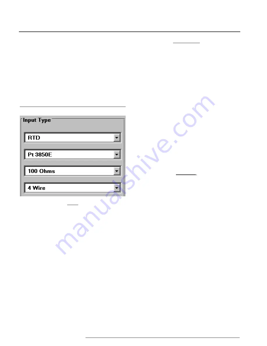
Input Type
values as shown in Figure 4. Continue to change
the remaining areas in
Input Type
(such as
ohms, linearization, custom table, or # wires,
depending on your sensor type).
Figure 4.
Choosing the Input Type for the TDY .
IMPORTANT:
Settings on the Configuration Program Screen do
not take effect in the unit until the Configuration File
is downloaded. Skip to Step 6 for instructions on
getting the settings programmed
into TDY nonvolatile memory.
2. Select one of these options:
a. Download the current settings into the
connected transmitter’s memory (Go to Step
3),
b. Continue creating a Configuration File by
setting other parameters, or
c. Save the current settings into a file on disk for
later downloading to a transmitter(s). Refer to
“Keeping What You’ve Got Safe”, starting with
Step 3 on page 9.
3. To start the Download Process, click on
the “Stop” button at the bottom-center of
the screen, then on the “Prog” button. This
transfers the settings from the software to the
memory of the connected transmitter.
CAUTION
:
Any time a connected TDY is “programmed”
by downloading a Configuration File into memory,
ALL of the configuration parameters resident
in the transmitter memory at the time of the
download are OVERWRITTEN. These previous
parameters are unrecoverable. This includes things
like tag name, calibration date, trim values, etc.
The Status Bar in the upper-left corner of the
Configuration Program screen will display the
progress of the download of the Configuration
File to the connected transmitter.
When the download is complete, the
Configuration Program will emit a faint, yet
distinctly audible “beep” to indicate that the
download was successful.
4. Click on the “Start” button to re-enable the
Configuration Program’s monitoring of the
connected transmitter.
The status area of the Configuration Program
screen will display the “Measurement ON”
message, and will show the trimmed values
resident in memory.
Note:
The TDY Custom Input Linearization Table facility is
available only with the “Millivolts” input selection.
RTD input selections distinguished by the “E” suffixed
alpha value selections use 128-bit linearization curves.
RTD selections without the “E” suffix use standard,
32-bit curves. 128-bit curves are only available with a
TDY connected to the PC.
Summary of Contents for TDY
Page 32: ...TDY 32 Demand Moore Reliability...


