TDY
12
Demand Moore Reliability
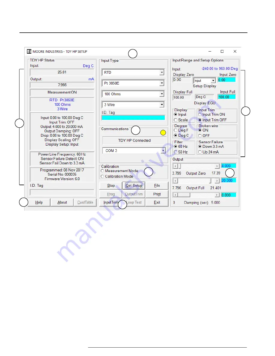
1. TDY HP Status
The left column of the screen
displays the input, output, and settings of the TDY.
This column will change to reflect the values on the
rest of the screen when you program the TDY with its
new values.
2. Calibration
Use these radio buttons to change
from “Measurement Mode”, the mode that you will be
doing all your work from the PC in, and “Calibration
Mode”, the mode that you will select when using a
handheld calibrator to simulate input to the unit.
3. “Help” Buttons
The “Help” and “About” buttons
both provide information on the TDY Configuration
Software. The “CustTable” button allows you to set up
a custom linearization table for your TDY.
4. File Management Buttons
This set of nine
buttons are essential to all the functions of the
Configuration Software, and will be used often. The
names and functions of the individual command
buttons may change when you press a button.
5. Output
These scroll bars control the scaling and
damping values of the TDY. When certain options are
selected, these scroll bars are renamed to adjust the
reverse output and the loop test.
6. Input Range and Setup Options
Use this section
to configure the TDY’s range of input and parameters
of its display options.
7. Input Type
The top pull-down menu of this section
selects the type of input that the TDY will accept:
Millivolt, Ohms, RTD, Thermocouple, or Potentiometer.
The pull-down menus below it change to provide only
the options for the input type you have selected.
8. Communication
The communication menu
displays the status of the TDY: if it is connected, and
to which COM port it’s connected to. The yellow light
in the upper right corner of this section will flash if the
TDY is connected.
Figure 3.
PC Configuration Software Screen Summary
3
1
2
8
7
6
5
4
Summary of Contents for TDY
Page 32: ...TDY 32 Demand Moore Reliability...


