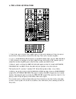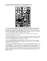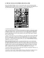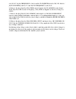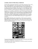
waveform. Vary the FREQUENCY control and the WAVEFORM switch of the 921. Return
the WAVEFORM switch to ??? and the 921 FREQUENCY control to 0.
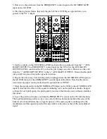
6. Remove the plug from the 921A FREQ control input to the 921A WIDTH control input.
Notice that the width, instead of frequency, of the 921B rectangular waveform is being con-
trolled.
7. Remove the plug from the 921A WIDTH control input to a 904A CONTROL INPUT.
Turn the 904A FIXED CONTROL VOLTAGE to 3. Turn REGENERATION to 6. The over-
tone content of the 921B waveform is now voltage controlled. Return the FIXED CONTROL
VOLTAGE to 6.
8. Remove the plug from the 904A CONTROL INPUT and insert it in a 902 CONTROL IN-
PUT. Turn the FIXED CONTROL VOLTAGE to 3. The amplitude of the 921B waveform is
now voltage controlled.
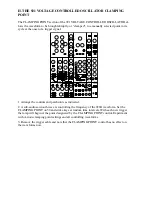
In situations using voltage control, the module’s operating point (effective control voltage) is
determined by the sum of the applied control signals and the fixed control voltage. The fixed
control voltage is determined by the module’s panel control.

