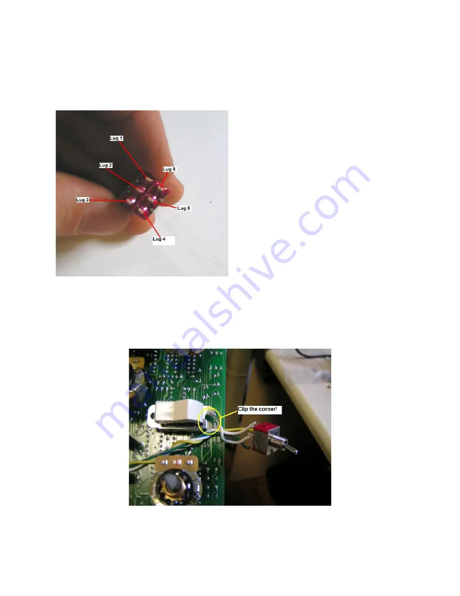
The above picture shows a good length for the switch wiring. Wire the switch as follows
1. Wire U2 pin 16 (+15V) to lug 1.
2. Wire U2 pin 10 to lug 2.
3. Wire 'N' control signal (cathode hole) to lugs 3 & 4.
4. Wire D1 cathode to lug 5.
(Switch Lug 6 remains disconnected from circuit)
5. After wiring up the switch, you can add the jacks and power to the PCB and test the Spillover
switch. Be careful handling the raw PCB. Don't let anything short out!
6. To Make room for the switch, you'll need to clip off the edge of the Int/Ext switch hardware.
Use sharp cutters and don't over-stress the Int/Ext switch. It can break easily!
7. Add a dab of silicone glue to D1 on the PCB to keep it in place


