


- 2 -
!
!
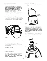
Loosen screws only,
do not remove
Remove dome by twisting
counter-clockwise until it
stops, then pull down
DESCRIPTION:
The RH7C Housing is a Vandal Resistant Housing especially
designed for integrated pan/tilt units. The housing top is made of
high impact resistant cast aluminum while lower dome is made of an
optically clear, UV stable, polycarbonate plastic. The RH7C housing
measures 9.75” (w) x 13 (h) and 14.5” (d) with a weight of 8.25 lbs.
Flying leads are provided for all power, control and video connec-
tions. The leads are supplied with a standard BNC and (2) screw
down connectors. Two 25W heater (50 watts total) with (2) circula-
tion fans also supplied.
ELECTRICAL SPECIFICATIONS (OUTDOOR ONLY):
Power 24VAC, Class 2 Only
52 watts at 24 VAC (accessories)
Heater: 50 watts
Blower: 2 watts
Input Connectors (outdoor units):
BNC
(2) screw-down connectors
NOTE:
This unit is designed for operation in an upright
position. Installing the RH7™ upside down may
cause damage to the internal equipment, and
will void the warranty.
PARTS LIST
Check to be sure the following parts are included.
1. Housing
2. Housing Packet
a. (2) Mates for screw down connectors (not supplied with
indoor units)
b. (1) Adapter plate
c. (8) 1/2" standoffs
d. (8) 8 x 32 x 3/8" Mounting screws with star washers
e. (3) 6 x 32 x 3/8" Mounting screws with star washers
f. (2) 1/4 x 20 x 3/8" HH Bolts
g. (2) 1/4” Flat washers
h. (2) 1/4" Split Lock washers
i. Instruction Manual
TABLE OF CONTENTS
Description
1
Electrical Specifications
1
Parts List
1
Installing Quick Release Bracket
1
Installing the Housing Assembly
1
Installing Optional Pendant Mount
2
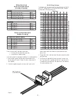
Wiring Color Code Chart
2
Instructions for Quick Release Brackets
4
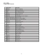
Exploded View
5
Exploded View for Replacement Parts
6
Mounting Template
8
Safeguards and Warranty Information
9
Be sure the bracket is properly and securely mounted to a
supporting structure capable of rigidly holding the weight of
the entire unit.
INSTALLING QUICK RELEASE BRACKET AND PAN/TILT
CAMERA ASSEMBLY (ALL MODELS)
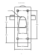
1. Open the housing by loosening the (3) tamper proof screws
located on the housing ring next to the lower clear dome
(Figure 1). Be careful not to back these all the way out. Twist the
dome slightly in a counterclockwise motion until it stops, then pull
down to remove.
2. Install the pan/tilt unit quick-release bracket.
It is recommended
that this be done before installing the housing
. Instructions for
mounting quick-release brackets from selected manufacturers are
on page 4.
3. Clean the inside of the dome. Reattach the housing dome and
secure the (3) captive screws.
Do not overtighten the screws
.
Tighten only to the point at which the gap between the ring and
the housing top closes.
GENERAL INSTRUCTIONS:
Tools Required: .100" Flat Head Screwdriver
Phillips Head Screwdriver
Figure 1


