background image

- 4  -

22

250

120

89

65

44

35

29

25

31

19

17

16

14

13

12

11

11

10

9

9

8

20

400

180

141

90

70

56

47

40

34

31

28

25

23

21

20

18

17

16

15

14

14

18

600

300

225

130

112

90

75

64

55

50

45

41

37

34

32

30

28

26

25

23

22

16

960

480

358

225

179

143

119

102

85

79

71

65

59

55

51

47

44

42

39

37

35

14

-

800

571

350

285

228

190

163

140

126

114

103

95

87

81

76

71

67

63

60

57

12

-

1300

905

525

452

362

301

258

215

201

181

164

150

139

129

120

113

106

100

95

90

10

-

-

1440

830

720

576

480

411

340

320

288

261

240

221

205

192

180

169

160

151

144

5.5

10

20

30

40

50

60

70

80

90

100

110

120

130

140

150

160

170

180

190

200

Maxim

um distance fr

om transf

ormer to load

Total vA

consumed

Wire Gauge

                              24k VAC Wiring Distances

The following are the recommended maximum distances for 24 VAC
with a 10% voltage drop (10% is generally the maximum allowable
voltage drop for AC powered devices).

Wiring Color Code

Power and Control Inputs

(Outside of housing)

Power and Control Outputs

(Inside of housing)

POWER

1

Camera Power (24 VAC)

Red

2

Camera Power (24 VAC)

Orange

3

Accessory Power (24 VAC)

Yellow

4

Accessory Power (24 VAC)

Green

CONTROL

1

RS-485RXB

Blue

2

RS-485RXA

Violet

3

RS-485TXA

Gray

4

RS-485TXB

White

POWER AND CONTROL LEADS

1

Camera Power (24 VAC)

Red

2

Camera Power (24 VAC)

Orange

3

RS-485RXB

Blue

4

RS-485RXA

Violet

5

RS-485TXA

Gray

6

RS-485TXB

White

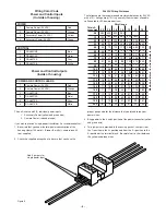
The unit is setup with (2) individual power inputs.

1.

Accessory Power (yellow and green wire)

2.

Camera Power (red and orange)

If you wish to provide a single power transformer it is recommended that:

1.  Be certain that you know the total power consumption of the 

housing Heater (50 watts) + Blower (2 watts) + camera/pan-tilt

(not  supplied) 

2.  Check the supplied wiring chart to be sure that you have the 

     proper gauge wire for the distance that you intend to run your 

     power wires. 

3.  Bring power to the 3 and 4 position of the power connector (yellow 

     and green wire) 

4.  Two jumpers are provided in the housing packet.  Jumper from 

the 1

st

 position to the 3

rd

 position and from the 2

nd

  position to the 

4

th

 position of the terminal block.  Be careful not to short between 

the yellow and green wires.

Figure 5

Add 2 jumpers for 
single power input

Summary of Contents for RH7

Page 1: ... Series Installation and Operation Instructions for the following models Before attempting to connect or operate this product please read these instructions completely CERTIFIED 81 IN5300 02 02 2009 2009 Videolarm Inc All Rights Reserved ...

Page 2: ...ing screws with star washers f 2 1 4 x 20 x 3 8 HH Bolts g 2 1 4 Flat washers h 2 1 4 Split Lock washers i Instruction Manual TABLE OF CONTENTS Description 1 Electrical Specifications 1 Parts List 1 Installing Quick Release Bracket 1 Installing the Housing Assembly 1 Installing Optional Pendant Mount 2 Wiring Color Code Chart 2 Instructions for Quick Release Brackets 4 Exploded View 5 Exploded View...

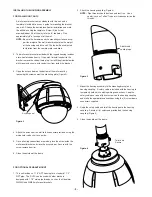
Page 3: ...ned with 1 1 2 male pipe threads such as the Videolarm WM20G and WM20 wall mount brackets 4 Attach the wires from the wall to the connector provided using the wiring color code chart as a guide 5 Once all wiring connections are made place the wires inside the wall mount bracket and close the access door Secure with the screw removed earlier 6 Clean the outside of the dome Figure 2 Access panel 3 O...

Page 4: ... 1 Camera Power 24 VAC Red 2 Camera Power 24 VAC Orange 3 Accessory Power 24 VAC Yellow 4 Accessory Power 24 VAC Green CONTROL 1 RS 485RXB Blue 2 RS 485RXA Violet 3 RS 485TXA Gray 4 RS 485TXB White POWER AND CONTROL LEADS 1 Camera Power 24 VAC Red 2 Camera Power 24 VAC Orange 3 RS 485RXB Blue 4 RS 485RXA Violet 5 RS 485TXA Gray 6 RS 485TXB White The unit is setup with 2 individual power inputs 1 A...

Page 5: ...uires use of the adapter bracket supplied in the housing packet Attach 4 of the 1 2 standoffs to the main housing bracket Put the adapter bracket in place and secure it with 4 8 x 32 x 3 8 bolts and star washers Align the Ultra Dome quick release bracket as shown and secure in place with 2 10 x 32 x 3 8 bolts and star washers Wire as directed by the manufacturer A wiring color code is supplied on ...

Page 6: ... 19 1 4 Lock Washer 92 WSSL01 4 20 1 4 x 20 x 75 Hex Head Bolt 90 BTHH27 4 21 10 x 32 x 375 Bolt 90 BTRP20 4 22 WM10 Wall Mount Bracket 50 WM10G GRAY 1 22a WM10 1 Hole Plug 94 FSHP06 1 n s Housing Packet 40 PKRH7 1 28 27 26 25 24 23 22 21 20 19 18 17 EXPLODED VIEW OF HOUSING 1 22 21 20 19 18 17 16 15 14 13 12 11 10 8 7 6 5 2 17 1 4 x 20 FH SS Bolt 90 BTSR01 1 18 Housing Pendant Bracket 30 VL926 1 ...

Page 7: ... 7 1 9 2 3 5 4 6 8 7 10 14 16 15 7 12 11 SEE PACKET ASSEMBLY 13 RH7 RH7N Exploded Diagram for Replacement Parts ...

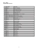
Page 8: ...odel RH7NHB Connection PCB Network Models 7 RPFD060 Camera Bracket 8 RPFD040 Upper Bracket Assembly 9 RPRH709 Housing Top Gray RPRH710 Housing Top White 10 WM10 WM10 Wall Mount 11 RPNET01 Network Camera Brackets 12 RPNET02 Network Housing Power Board 13 RPRH713 RH7 Fixed Bracket 14 SD0180 Pendant Housing Coupling 15 SD0170 Quick Release Pipe Coupling 16 SD0160 Pendant Mount Kit Items Not Shown RPR...

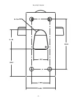
Page 9: ... 9 2 000 3 250 R 733 2 132 2 981 1 537 5 500 Mounting Template ...

Page 10: ...l of the following terms and conditions 1 NOTIFICATION OF CLAIMS WARRANTY SERVICE If Purchaser believes that the Product is defective in material or workmanship then written notice with an explanation of the claim shall be given promptly by Purchaser to Videolarm but all claims for warranty service must be made within the warranty period If after investigation Videolarm determines that the reporte...

Page 11: ...n Form at www videolarm com productregistration jsp or complete and mail in the bottom portion of this flyer Register your recent Videolarm purchases and benefit from the following Simple and Trouble Free RMA process Added into customer database to receive product updates news Eliminate the need to archive original purchase documents Receipts Purchase Orders etc Main Contact Info First Name Last Nam...

Reviews: