


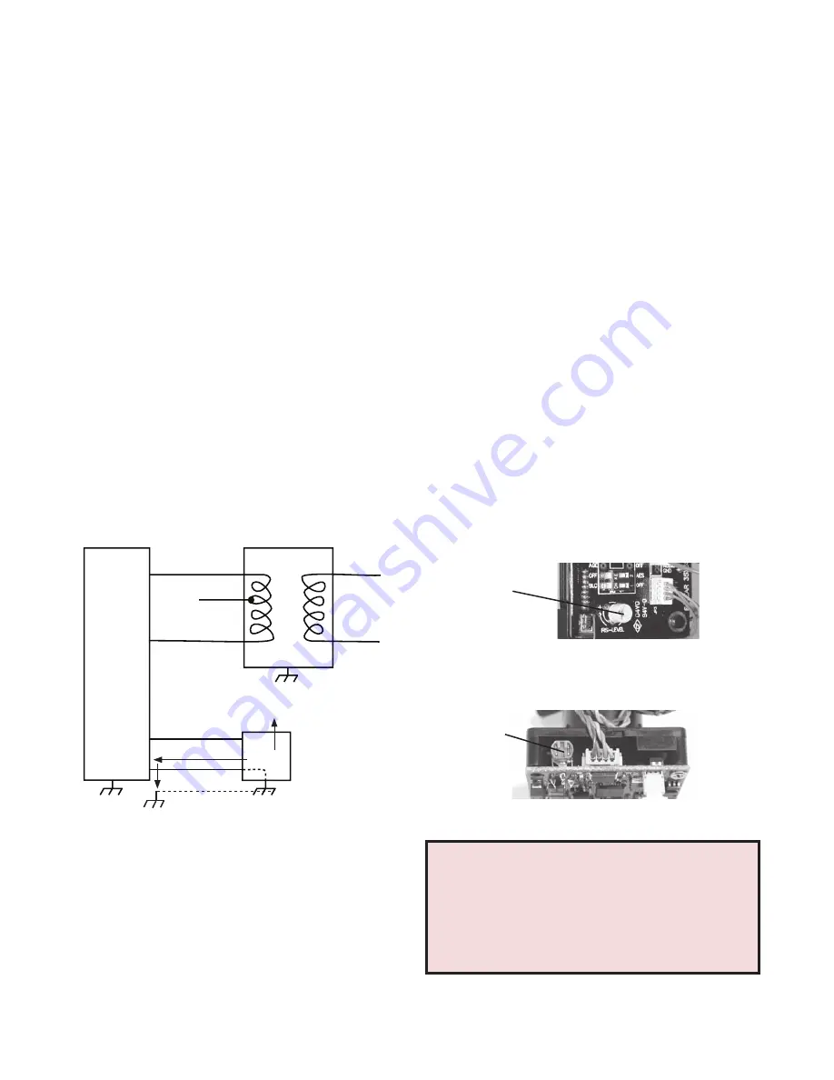
Power Supply
Power A
Power B
Camera
Assembly
Primary
Power
Video Signal
Video Shield
Monitor
(Ground Return)
Figure A Ground Loop
TROUBLESHOOTING
If you experience problems with the camera picture please check these simple
troubleshooting procedures for possible solutions before calling technical support.
IMPORTANT NOTE:
If you have removed the ground loop and the horizontal line still
remains on screen call Moog Videolarm technical support for further information.
GROUND LOOPS
Generally a horizontal line on screen, whether moving or stationary, means you have a
ground loop problem. The video shield should only be connected to ground through the
monitor or other electronic equipment that uses the video signal. Connecting the video
shield to ground at the camera will create a ground loop, which may interfere with the
video signal (See Figure A). This should not damage the camera, but the video signal
may become unusable. A ground loop problem will cause a dark horizontal bar to slowly
“scroll" through the picture. To solve this problem, remove all ground connections from
the video connection EXCEPT for the ground at the terminating end of the video signal.
The video termination should be a 75-ohm impedance, standard in monitors and other
video equipment. If the video signal goes to more than one piece of equipment, a monitor
and multiplexer input for instance, insure that one and only one piece of equipment
terminates the video signal with 75 ohms; otherwise the image will be degraded and
may appear to be unusually dim.
STATIONARY OR SCROLLING HORIZONTAL LINES
ON SCREEN
PICTURE IS CLEAR, LOW OR NO COLOR;
PICTURE IS DARK OR GRAINY IN GOOD
LIGHTING CONDITIONS
The auto iris lens is set at the factory. If you experience video too light or dark you can
manually adjust using the auto iris adjustment screw.
If there is low or no color the Auto Iris is too open, if the picture is
dark or grainy in good conditions the Auto Iris is too closed.
To adjust the auto iris lens, first locate the AUTO IRIS ADJUSTMENT SCREW on the camera
PC board. Using a small insulated
screwdriver (blade width of from 1/16" to 3/32"), adjust the control. Turning the control
CLOCKWISE opens the iris, making the image brighter.
Turning the control COUNTER CLOCKWISE closes the iris, making the image darker.
Figure D
AUTOMATIC BROWN OUT FEATURE
The camera includes an automatic brown out feature which is activated whenever the
incoming voltage drops below 10 VAC or VDC.
IMPORTANT NOTE ON AUTO IRIS ADJUSTMENT:
WHEN ADJUSTING, USE A SMALL, INSULATED SCREWDRIVER
. The auto iris
adjustments are very sensitive. Use gentle pressure when turning. To adjust, turn
either clock-wise or counter-clockwise no more than one degree at a time. Check
the monitor after each turn to determine is the desired brightness and color have
been obtained. When the adjustment is satisfactory, place a hand over the lens to
block out all light. Quickly remove the hand to be sure the iris reacts.
LINE LOCK
All cameras are all shipped from the factory with the line lock function disabled. If your
application requires Line Lock contact Videolarm.
Auto Iris
Adjustment
Screw
COLOR & DAY/NIGHT AUTO-IRIS
Figure B
BLACK & WHITE AUTO-IRIS
Auto Iris
Adjustment
Screw


