background image

11.


Channels 1-5 BASS Controls: Cuts or boosts the low frequency output of each 
individual Channel. The adjustment range is -10dB to +10dB. 

12.


Channels 1-5 LEVEL Knobs: Adjusts the volume level for each individual Channel. 

13.


Media Player: The Media Player consists of a built-in FM tuner and an mp3 player 
with an associated SD™ card slot USB port. See the 

Media Player Controls 

section for operating details. 


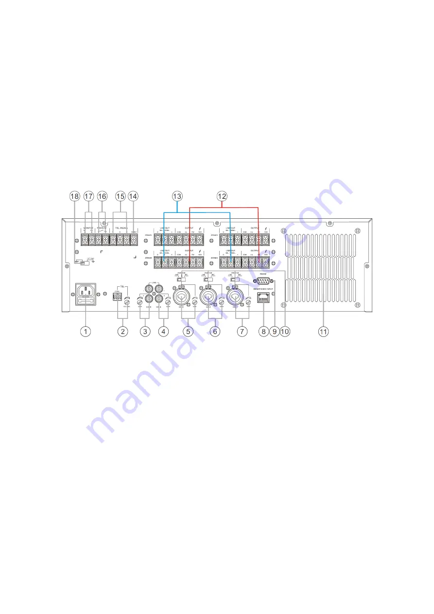
Rear Panel 


1.


AC Input Connector and Fuse Holder: Plug the included AC power cord into the 
panel connector. To change the fuse, use a small screwdriver to pry the fuse 
holder open. A spare T12AL 250V fuse is included inside the fuse holder. 

2.


TELephone Zone Selector DIP Switch and VOLUME Control: Selects which Zones 
that the Telephone input will broadcast and adjusts to the Telephone input 
volume level. 

3.


Channel 5 Line Input and GAIN Control: Stereo RCA connectors for the Channel 5 
Line input and control for adjusting the amount of gain to apply to the input. 

4.


Channel 4 Line Input and GAIN Control: Stereo RCA connectors for the Channel 4 
Line input and control for adjusting the amount of gain to apply to the input. 

5.


Channel 3 Input and GAIN Control: Combination XLR/TRS connector for the 
Channel 3 input and control for adjusting the amount of gain to apply to the 
input. 

Summary of Contents for 18802

Page 1: ...Commercial Audio 4x 120 watt 5 channel 4 zone 100 70V Mixer Matrix Amplifier with Digital Media Player P N 18802 User s Manual ...

Page 2: ...EDANCE SPEAKER SYSTEMS 11 INSTALLATION 13 Speaker Connections 13 Line Out Connections 14 Connecting a Telephone Paging System 15 FM Antenna Connection 15 Monitor Connection 16 Setting Priority 16 Microphone and Line Connections 17 RS 232 Connection 17 Power Connection 17 Sample Connection Diagram 18 Block Diagram 19 INITIAL SETUP 20 OPERATION 22 Channel and Zone Controls 22 Media Player Controls 2...

Page 3: ...3 Bluetooth Connection 24 FM Playback 24 MP3 Recording 24 RS 232 Control 25 SPECIFICATIONS 29 TECHNICAL SUPPORT 30 REGULATORY COMPLIANCE 30 Notice for FCC 30 Notice for Industry Canada 31 ...

Page 4: ...ireplace stove radiator etc Do not leave it in direct sunlight This device ventilates excessive heat through the slots and openings in the case Do not block or cover these openings Ensure that the device is in an open area where it can get sufficient airflow to keep from overheating Do not place or install this device in an area where it can be exposed to excessive amounts of dust humidity oil smo...

Page 5: ...emical cleaners solvents or detergents For stubborn deposits moisten the cloth with warm water This device has no user serviceable parts Do not attempt to open service or modify this device If using this amplifier to drive a 70V or 100V speaker array ensure that the total wattage rating of the speaker array does not exceed 80 of the amplifier s rated RMS power level i e 96 watts Because high volta...

Page 6: ... switch It can also interface with external phone systems for telephone paging FEATURES Four independent 120 watt amplifiers capable of driving 4Ω loads as well as 70V or 100V constant voltage speaker arrays Three combination XLR TRS balanced unbalanced inputs capable of connecting microphone level microphone level with Phantom power or line level sources Two unbalanced stereo RCA inputs Independe...

Page 7: ...noprice Customer Service representative through the Live Chat link on our website www monoprice com or via email at support monoprice com Check the website for support times and links PACKAGE CONTENTS Please take an inventory of the package contents to ensure you have all the items listed below If anything is missing or damaged please contact Monoprice Customer Service for a replacement 1x 5 chann...

Page 8: ...cators show the output level for each of the four Zones 6 Zone 1 4 Monitor Buttons Buttons to enable or disable the Monitor for each of the four Zones The button will illuminate when selected 7 Zone 1 4 LEVEL Knobs Adjusts the individual volume level for each of the four Zones 8 Power Switch Powers the amplifier on or off 9 POWER PROTection LED Indicator The LED illuminates blue when the amplifier...

Page 9: ...l screwdriver to pry the fuse holder open A spare T12AL 250V fuse is included inside the fuse holder 2 TELephone Zone Selector DIP Switch and VOLUME Control Selects which Zones that the Telephone input will broadcast and adjusts to the Telephone input volume level 3 Channel 5 Line Input and GAIN Control Stereo RCA connectors for the Channel 5 Line input and control for adjusting the amount of gain...

Page 10: ...position for input from a condenser microphone that needs 48V phantom power 11 Cooling Fan Cooling fan and ventilations holes Do not cover the ventilation holes 12 Zones 1 4 OUTPUT Connectors Speaker connectors for the output of each individual Zone 13 Zones 1 4 LINE OUTputs Balanced and unbalanced line output connectors for each individual Zone Whatever is being output to the speakers will be out...

Page 11: ... function at distances up to 26 feet 8 meters and at angles up to 35 degrees horizontally and 15 degrees vertically CONSTANT VOLTAGE VS LOW IMPEDANCE SPEAKER SYSTEMS A constant voltage speaker system differs from a traditional low impedance e g 8 ohm speaker system in that it uses a step up transformer at the audio source to raise the voltage and lower the current on the transmission line At the s...

Page 12: ...e it further producing either a 24 ohm or 2 67 ohm overall impedance Note that very few amplifiers are stable under 2 ohm loads so that is usually not an option On the other hand with a constant voltage system you consider first the RMS output wattage of the amplifier This should be reduced by 20 to compensate for insertion loss Each individual speaker on a given channel is set to a value such tha...

Page 13: ... Lift the bottom of the terminal cover over the Zone 1 OUTPUT connectors Using a flat head or Phillips screwdriver loosen the COM screw then loosen the 4Ω 70V or 100V screw depending on the type of speaker array being connected Note that only one type of connection can be used for each zone 3 Insert the stripped end of the negative speaker wire lead for the first speaker array under the COM screw ...

Page 14: ... over the Zone 1 LINE OUT connectors 3 If making an unbalanced connection use a flat head or Phillips screwdriver to loosen the G and screws If making a balanced connection loosen the screw as well 4 Insert the positive lead under the screw plate then tighten the screw 5 If making an unbalanced connection insert the negative lead under the G screw plate then tighten the screw If making a balanced ...

Page 15: ...om the telephone system under the T screw plate then tighten the screw 6 Flip the terminal cover for the TEL PAGING connectors down then press on the bottom to click it into place 7 For those Zones you want to receive telephone paging broadcasts slide the corresponding numbered DIP switch up to the ON position Slide the other DIP switches down toward the numbers FM Antenna Connection Perform the f...

Page 16: ...ity By default the priority order of inputs is as follows Channel 1 Telephone Channel 2 Channel 3 Channel 4 Channel 5 Media Player When the priority input contacts are closed shorted the priority order is Telephone Channel 1 Channel 2 Channel 3 Channel 4 Channel 5 Media Player Perform the following steps if you wish to have the Telephone input take priority over Channel 1 1 Lift the bottom of the ...

Page 17: ...position 3 Repeat steps 1 and 2 for the CH 2 and CH 3 inputs as desired 4 Plug the left RCA output of your line level source into the CH 4 L RCA jack then plug the right RCA output into the CH 4 R RCA jack 5 Repeat step 4 for the CH 5 input as desired RS 232 Connection A 9 pin DE 9 aka DB 9 serial connector is provided which you can connect to a computer for automated control Perform the following...

Page 18: ...18 Sample Connection Diagram ...

Page 19: ...19 Block Diagram ...

Page 20: ... is displayed 7 Press and hold the MODE button until the display starts blinking the year 8 Using the button to increase the displayed value or the button to decrease the displayed value set the displayed year to the current year 9 Press the MODE button and the display will change to show the month and date with the month flashing Use the and buttons to set the displayed month to the current month...

Page 21: ... audio source 20 Press the Z1 button in the CH 1 section to enable output of CH 1 audio to Zone 1 21 Using a small flat head screwdriver slowly adjust the CH 1 GAIN control on the rear panel alternately with the CH 1 LEVEL control on the front panel until the volume level matches that of the FM tuner both audio sources should be simultaneously audible on the Zone 1 speakers 22 Press the CH 1 Z1 bu...

Page 22: ...ls effectively mix and balance the five inputs 4 MUTE Button Press the MUTE button to mute the CH 2 audio source The LED above the button will glow when MUTE is enabled 5 ZONE Buttons Directs the output of CH 2 audio to any or all of the four Zones When a Zone is enabled the button will glow blue 6 ZONE 1 LEVEL Knob Adjusts the overall output volume level for Zone 1 7 MON Button Press the MON butt...

Page 23: ...ive is connected 3 LCD Display The LCD Display shows the track number and play time When the media player is not being used the LCD Display will show the current time 4 Previous Track Button Momentarily press the button to skip back to the previous track Press and hold the button to decrease the volume level of the media player 5 Play Pause Button With an audio track playing momentarily press the ...

Page 24: ...w for improved reception 2 Momentarily press the MODE button until an FM frequency is shown on the LCD Display 3 Perform one of the following methods for tuning an FM station Momentarily press the button to automatically scan for an FM station The scan will stop on the first station with a sufficiently strong signal Momentarily press the button again to continue the scan until you find a station y...

Page 25: ...onds to the following commands 1 PC serial port issued instructions to get button data Instructions FF 05 00 05 2 PC serial port issued instructions for the LED indicator Instructions FF 05 01 06 3 PC serial port instructions for setting the priority level Instructions FF 05 02 07 4 PC serial port issue instructions of get telephone the remote switch Instructions FF 05 04 09 5 PC serial port issue...

Page 26: ... PC serial port issue instructions of control CH1 connection ZONE4 OPEN FF 06 88 8E CLOSE FF 06 08 0E 13 PC serial port issue instructions of control CH3 connection ZONE1 OPEN FF 06 89 8F CLOSE FF 06 09 0F 14 PC serial port issue instructions of control CH3 connection ZONE2 OPEN FF 06 8A 90 CLOSE FF 06 0A 10 15 PC serial port issue instructions of control CH3 connection ZONE3 OPEN FF 06 8B 91 CLOS...

Page 27: ...2 PC serial port issue instructions of control CH2 connection ZONE2 OPEN FF 06 92 98 CLOSE FF 06 12 18 23 PC serial port issue instructions of control CH2 connection ZONE3 OPEN FF 06 93 99 CLOSE FF 06 13 19 24 PC serial port issue instructions of control CH2 connection ZONE4 OPEN FF 06 94 9A CLOSE FF 06 14 1A 25 PC serial port issue instructions of control CH4 connection ZONE1 OPEN FF 06 95 9B CLO...

Page 28: ...2 OPEN FF 06 9A A0 CLOSE FF 06 1A 20 31 PC serial port issue instructions of control CH5 connection ZONE3 OPEN FF 06 9B A1 CLOSE FF 06 1B 21 32 PC serial port issue instructions of control CH5 connection ZONE4 OPEN FF 06 9C A2 CLOSE FF 06 1C 22 33 MP3 Mute OPEN FF 06 9D A3 CLOSE FF 06 1D 23 34 CH1 Mute OPEN FF 06 A2 A8 CLOSE FF 06 22 28 35 CH2 Mute OPEN FF 06 9E A4 CLOSE FF 06 1E 24 36 CH3 Mute OP...

Page 29: ... Input Sensitivity and Impedance CH1 CH2 CH3 MIC 2 5mV 600Ω CH1 CH2 CH3 PHANTOM 2 5mV CH1 CH2 CH3 LINE 175mV 10kΩ CH4 CH5 LINE 350mV 10kΩ TEL 350mV 10kΩ Line 1 4 Output Level 1V 600Ω SD Card Support SD card up to 32GB capacity formatted for FAT16 or FAT32 with all mp3s in root directory Does not support file folders Input Power 120 VAC 50 60 Hz Maximum Power Consumption 750 watts Dimensions 19 1 x...

Page 30: ...oprice s authorization may result in the equipment no longer complying with FCC requirements for Class B digital devices In that event your right to use the equipment may be limited by FCC regulations and you may be required to correct any interference to radio or television communications at your own expense This equipment has been tested and found to comply with the limits for a Class B digital ...

Page 31: ...at to which the receiver is connected Consult the dealer or an experienced radio TV technician for help Notice for Industry Canada This Class B digital apparatus complies with Canadian ICES 003 Cet appareil numérique de la classe B est conforme à la norme NMB 003 du Canada SD is a trademark or registered trademarks of SD 3C LLC in the United States other countries or both ...

Reviews: