background image

11 

SETUP 

Once all connections have been made and inspected, plug in and power on all equipment, 
including the subwoofer. 
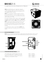
 

Subwoofer Settings 

Auto Power: The amplifier features a power saving mode, which will automatically put 
the amplifier into standby mode after about 22 minutes of inactivity, then will 
automatically power on when an audio signal is detected. Use the POWER and AUTO 
switches to determine the mode of operation, as outlined below: 
 

Mode 

POWER Switch 

AUTO Switch 

LED 

ALWAYS OFF 

OFF 

N/A 

Off 

STANDBY 

ON 

ON 

Red 

AUTO ON 

ON 

ON 

Green 

ALWAYS ON 

ON 

OFF 

Green 

 
Note: If you will be away, or if the subwoofer will go unused for a lengthy period, set 
the power switch to the OFF position. 
 
Frequency: The Frequency knob allows you to adjust the frequency of the low pass 
filter, which acts as a crossover network between the subwoofer and satellite/center 
channel speakers. This setting determines how well the bass from the subwoofer 
blends with the mids and highs from the satellite and center channel speakers.  
Refer to the owner's manual for your satellite/center channel speakers to find the low 
end of the frequency response. A good starting point therefore is to set the Frequency 
knob to a position that represents that level, then adjust it slightly up or down 
according to how it sounds. 


Summary of Contents for 14567

Page 1: ...MONOPRICE Select 8 inch 200 watt Subwoofer PID 14567 30734 30735 User s Manual...

Page 2: ...8 Connecting to a Dedicated Subwoofer Output 9 Connecting to a Stereo Preamplifier Output 9 Connecting to a Stereo Speaker Output 10 SETUP 11 Subwoofer Settings 11 INPUT VOLTAGE AND FUSE REPLACEMENT...

Page 3: ...not place or install this speaker near a heat source such as a fireplace stove or space heater Ensure that there is at least 8 20cm of free space in the back of the subwoofer to allow for heat dissipa...

Page 4: ...move power and unplug the subwoofer before attempting to replace the fuse Do not bypass the purpose of the fuse by shorting the contacts or by any other means Install the subwoofer in a place where th...

Page 5: ...r sound reproduction For best results please read this entire manual prior to installation and use To avoid personal injury or damage to your valuable equipment you should pay extra attention to the s...

Page 6: ...ket The fuse holder has the main fuse and a spare inside Check the SPECIFICATIONS table for the proper fuse ratings 2 POWER Depress the side with the white dot to turn power ON 3 VOLTAGE Use this swit...

Page 7: ...osts for connecting to the speaker level outputs on an amplifier This is the least favored method of connecting the subwoofer SPEAKER BREAK IN In the same way that a new car requires a break in period...

Page 8: ...amage to your equipment turn off and unplug all equipment before making connections Preparation Before attempting to make any connections it is best to look at the situation get all the necessary mate...

Page 9: ...ed Subwoofer Sub Pre Out or something similar on the back of the amplifier receiver Refer to the manufacturer s documentation for reference Subwoofer outputs are monophonic so if you have two subwoofe...

Page 10: ...al lengths of two conductor speaker wire 1 Connect the black negative side of one speaker wire to the left channel black negative High Level Input 5 way binding post on the back of the subwoofer 2 Con...

Page 11: ...S ON ON OFF Green Note If you will be away or if the subwoofer will go unused for a lengthy period set the power switch to the OFF position Frequency The Frequency knob allows you to adjust the freque...

Page 12: ...ill provide the best bass sound most of the time is with the phase set to 0 As the subwoofer breaks in you may find you need to make minor adjustments to the frequency and volume settings to ensure th...

Page 13: ...onal markets including the UK EU and Australia TROUBLESHOOTING Q There is no sound from the subwoofer A Ensure that the subwoofer is plugged into an AC outlet and that it is turned on Double check the...

Page 14: ...4 ohms 100Hz 0 5 Signal to Noise Ratio 96dB Line Input Sensitivity 205mV Adjustable Low Pass Crossover 46 250 Hz Low Pass Filter 270 Hz 30 dB oct High Pass Filter 28 Hz 22 dB oct Bass Boost 12dB 45 H...

Page 15: ...ursuant to Part 15 of the FCC Rules These limits are designed to provide reasonable protection against harmful interference in a residential installation This equipment generates uses and can radiate...

Page 16: ...of Conformity is available at the following internet address https www monoprice com product c_id 109 cp_id 10906 cs_id 1090602 p_id 1456 7 seq 1 format 2 or the CE DoC which can be found within this...

Page 17: ...s symbol and or its packaging must not be disposed of with unsorted municipal waste The symbol indicates that this product should be disposed of separately from regular household waste streams It is y...

Page 18: ...t with water or liquid might occurs WARNING Avoid using this product during an electrical storm There may be a remote risk of electric shock from the surge caused by lightning WARNING The external pow...

Reviews: