background image

30 

Basic Tab 

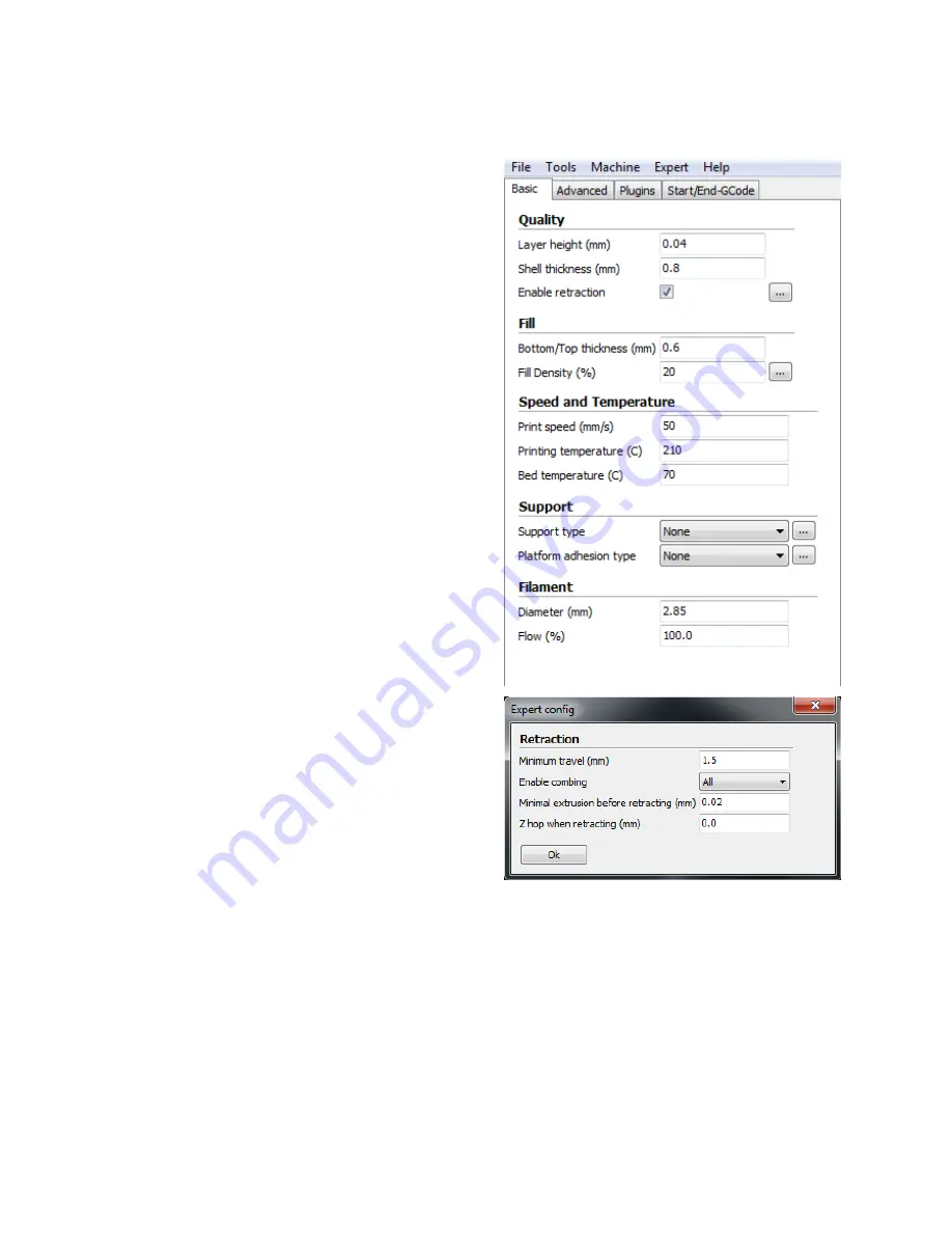
Click the Basic tab to view the basic build 
settings. 
Layer Height - The Layer Height determines the 
thickness of each printed layer. The smaller the 
layer height, the more layers will be needed 
and the more time will be required to print, 
but the printed object will have smoother 
curves and better detail. Larger layer heights 
are better for bridging and overhangs. 
Shell Thickness - Shell Thickness determines 
the number of vertical walls that comprise the 
outside of your model. We recommend that 
you limit this to multiples of your nozzle width, 
which is 0.5mm on this printer. 
Enable Retraction - When this option is 
enabled, the printer will retract filament from 
the end of the nozzle during non-printing 
moves/travels. We recommend that you keep 
this option enabled for all filament types and 
adjust the retraction length and speed for 
different filament types. Click the ... button to 
the right of the entry to adjust specific values. 
Refer to the 

Expert Settings section for 

Retraction settings details. 
Bottom/Top Thickness (mm) - This value determines the thickness of the bottom and top 
layers of your printed object. Thicker layers can improve strength and print quality, and can 
help with bridging. We recommend keeping this number to a multiple of your layer height. 
Fill Density (%) - This value determines the amount of material printed inside the object. A 
value of 0% will result in a completely hollow model, while a value of 100% results in a 
completely solid object. We have found that a value of 20% to 40% is good for most prints. 

Summary of Contents for 13860 Maker Select

Page 1: ......

Page 2: ...ll Settings View 29 Basic Tab 30 Advanced Tab 33 Plugins Tab 35 Expert Settings 37 TECHNICAL SUPPORT 43 REGULATORY COMPLIANCE 43 Notice for FCC 43 Notice for Industry Canada 44 APPENDIX A CONTROL BOX MENU REFERENCE 45 Main Menu 45 Quick Settings Menu 45 Position Menu 46 Extruder 46 Fan Speed 47 SD Card 47 Debugging 47 Configuration 48 Configuration General 48 Configuration Acceleration 49 Configur...

Page 3: ...ve vibration Do not expose this printer to water or moisture of any kind Do not place drinks or other containers with moisture on or near the printer If moisture does get in or on the printer immediately unplug it from the power outlet and allow it to fully dry before reapplying power Do not place the printer near a heat source such as a fireplace heating vent radiator etc The power supply for thi...

Page 4: ... print PLA ABS and other materials Open frame design for ease of use and maintenance Includes PLA filament for printing right out of the box Includes 4GB micro SD card with preinstalled sample 3D models CUSTOMER SERVICE The Monoprice Customer Service department is dedicated to ensuring that your ordering purchasing and delivery experience is second to none If you have any problem with your order p...

Page 5: ... i3 3D printer tower assembly with attached MK10 single step extruder 1x Monoprice i3 3D printer base assembly 1x Monoprice i3 3D printer power supply control box 1x Spool holder 1x Filament stand 1x 4mm hex wrench 6x Hex bolts 1x Putty knife 1x 4GB Micro SD card with sample 3D model files 2x Sheets of platform tape 1x Sample roll of PLA filament 10m 32ft 1x AC power cord NEMA 5 15 to IEC 60320 C1...

Page 6: ...is on the Quick Settings entry then press the knob to select it Next rotate the knob until the Home All entry is highlighted then press the knob to select it Most menus have a Back option to return to the previous menu If no option is available pressing the knob will often return to the previous menu Additionally the control box will automatically exit the menus and return to the home screen after...

Page 7: ...g and place it onto a flat surface 3 Remove the Power Supply Control Box and place it next to the base 4 Cut the white ribbon that secures the Extruder Assembly to the Tower Frame 5 Remove the Tower Frame and stand it up vertically on the flat surface ...

Page 8: ... four Hex Screws and the Hex Wrench Insert a screw into hole on the frame on the left side and tighten it using the hex wrench Repeat the process on the right side 8 Flip the printer onto its left side then insert a screw from inside the base and secure it to the frame using the hex wrench Flip the printer onto the other side and repeat the process ...

Page 9: ...not raise or lower either side by manually turning the Z axis couplers on either side of the frame 10 Remove one of the plastic nuts from the threaded end of the Spool Holder but leave the second nut in place Insert the threaded end of the spool holder through the Filament Stand from the side opposite the base support Thread the plastic nut onto the spool holder and tighten the plastic nuts on eac...

Page 10: ...s mounted over the center of the tower frame 12 The cable assembly on the left side of the base has three cables coiled and secured with a zip tie Carefully remove the zip tie then insert the white connector on the longest of the three cables into the white connector on the bottom of the X axis stepper motor 13 Mate the two pin black cable connector in the cable bundle with the corresponding black...

Page 11: ... corresponding white connector of the right side Z axis stepper motor 16 Use a lint free cloth to wipe the top of the aluminum build plate to ensure that no dust or other particles are present Remove the protective backing from one of the sheets of platform tape and carefully apply it to the platform ensuring that no bubbles are present Note that you can also use painter s tape or Kapton tape inst...

Page 12: ... Power Supply Control Box and flip it to the proper position as necessary 18 Ensure that the power switch is in the OFF position O side depressed Plug the C13 end of the included AC Power Cable into the C14 panel connector on the Power Supply Control Box then plug the other end into a nearby AC power outlet Depress the I side of the power switch to power the printer ON ...

Page 13: ... of the LCD display Select Quick Settings Home All Wait for the printer to move the build platform and extruder to the home position then turn the printer off 20 One by one squeeze each corner of the built platform and tighten the wingnut to compress the spring and reduce the distance between plates to the minimum ...

Page 14: ...t of ordinary printer paper as a guide The nozzle is at the correct height when you can just slide a single sheet of paper between the build platform and the nozzle To raise the build platform loosen the wingnuts under the build platform To lower the build platform tighten the wingnuts under the build platform Note that you may need to slightly squeeze the platform to more easily tighten the wingn...

Page 15: ...diately but will return to the home screen and display Preheat PLA at the bottom after about 30 seconds 24 Monitor the temperatures of the extruder and plate on the LCD display When they reach to within a few degrees of the targets you are ready to insert filament Note that the display will still show Preheat PLA even after the temperatures have reached the target values Carefully insert the inclu...

Page 16: ...s of filament material extrudes out of the nozzle Carefully clean the extruded filament material off the plate and nozzle 26 Insert the included MicroSD card into the slot on the side of the Power Supply then select SD Card Mount Card Finally select SD Card Print File select one of the sample 3D model files then press the knob to start printing Congratulations you have successfully setup your new ...

Page 17: ... a successful print Examine the extruded material and compare it to the following charts to determine if your build platform is a tad too high a tad too low or just right You may need to make several passes at height adjustment before you are ready for a large complicated print job ...

Page 18: ...18 ...

Page 19: ... Cura installation program go to the www monoprice com website type 13860 into the search bar then download the client from the product page Installation Perform the following steps to install the Cura program on your Windows PC 1 Unzip the installation file then run the executable Click the Next button to install Cura to the default location Otherwise click the Browse button to select a different...

Page 20: ...re is a check mark in all the boxes to install all elements then click the Install button to continue 3 The installer will unpack the files to prepare for the installation When it is done click the Next button to continue ...

Page 21: ...o verify you want to install the unsigned drivers Click the Install button to continue 5 Once the drivers are finished installing click the Finish button to continue installing the Cura client 6 Once the software has finished installing click the Next button to continue ...

Page 22: ...ure that there is a check mark next to the Start Cura entry then click the Finish button to continue 8 Once the client loads the First time run wizard will automatically launch Click the Next button to continue ...

Page 23: ... to the left of the Other Ex RepRap MakerBot Witbox entry By default the Submit anonymous usage information option is enabled If you do not want to participate remove the check mark from the box Click the Next button to continue ...

Page 24: ...24 10 Click the radio button to the left of the Prusa Mendel i3 entry then click the Next button to continue ...

Page 25: ...25 11 The Wizard will now save the machine settings Click the Finish button to complete the process 12 A Welcome dialog is now displayed Click the OK button to clear it from the screen ...

Page 26: ... High quality and Ulti quality Ultimate Try clicking the various options and note how the projected print time changes Material Select one of three different material options depending which type of filament you will be using The printer ships with sample PLA filament but you can also select ABS or U PET which is a newer filament material that combines the benefits of PLA and ABS Print Support Str...

Page 27: ...in the specified axis Additionally it reveals the Lay Flat and Reset buttons above the Rotate button Lay Flat Click the Lay Flat icon to ensure that the flat portion of your print is securely attached to the build platform It is highly recommended to do this after rotating the model in any axis Reset Click the Reset button to return the model its original orientation Scale When you click the Scale...

Page 28: ...allows you to look at the model from any angle View Modes Click the View mode button to reveal five view options for looking at your model in different ways Normal This is the normal view showing the outer portion of the model Overhang This view shows highlights in red those areas where your model could benefit from support structures Use this option to examine your model to make an informed decis...

Page 29: ...ayers or gaps in the model Drag the white button on the vertical layer selection bar to move up and down through the toolpath layers Full Settings View Click the Expert menu then click the Switch to full settings option This allows you to view and adjust all of the possible options to fine tune your print settings ...

Page 30: ...t from the end of the nozzle during non printing moves travels We recommend that you keep this option enabled for all filament types and adjust the retraction length and speed for different filament types Click the button to the right of the entry to adjust specific values Refer to the Expert Settings section for Retraction settings details Bottom Top Thickness mm This value determines the thickne...

Page 31: ...e If your print has angles or overhangs it could benefit from using support material We recommend orienting your model to minimize or eliminate the need for supports There are two types of supports possible Touching Buildplate and Everywhere The Touching Buildplate option only creates support for section of the model that are above the build platform as shown in the red model while the Everywhere ...

Page 32: ...the Brim and Raft options Refer to the Expert Settings section for option details Diameter mm This is one of the most important settings to get right This should be set to the average filament diameter specified by the filament manufacturer Flow This determines the amount of filament extruded in relation to the speed This is used to adjust for filament density variations We recommend leaving this ...

Page 33: ...ing range Initial Layer Thickness mm This value determines the thickness of the initial layer printed on the build plate A thicker initial layer can help prevent adhesion issues However adjusting this value can cause problems with the printer s leveling system so we recommend leaving this at the default values Adjust at your own risk Initial Layer Width mm This value determines the width of your f...

Page 34: ...is important because it affects the visible portion of your model Slower printing speeds are recommended for better looking prints Inner Shell Speed mm s This value determines the print speed when printing vertical walls between the outer shell and the infill We recommend keeping this setting between the values set for the Infill and Outer Shell speeds Minimal Layer Time sec This value determines ...

Page 35: ...lugin To activate a plugin highlight it and click the down arrow button to move it to the Enabled Plugins box Tweak at Z This plugin allows you to specify different settings for specific heights or layer counts Pause at Z Height This plugin allows you to tell the printer to pause printing when the model reaches a specific height or layer count This is most commonly used when changing filament colo...

Page 36: ...operations By adding custom Gcode into the start or end of your file you can alter how it prints A comprehensive list of Gcode commands can at http reprap org wiki G code We recommend that you leave this as provided by the printer profiles until you have gained more experience with Gcode ...

Page 37: ...over various functions and consolidates onto one dialog the various expert settings dialogs mentioned above Retraction The Retraction option allows the printer to retract filament from the end of the nozzle during non printing moves travels Minimum Travel mm The value specifies the minimum distance the printhead can move before filament retraction is performed ...

Page 38: ...rint Skirt The Skirt option prints one or more lines around the outside of your object This is primarily used to prime the extruder to prevent missed filament at the beginning of a print You should leave this on Line Count This value determines the number of loops that will printed around your object Smaller models should use a higher value to give the printer sufficient time to prime the extruder...

Page 39: ...he printhead if the minimum speed is activated because of a cooling slowdown Infill The Infill section sets fine details controlling infill printing Solid Infill Top When enabled you will have a solid top layer When disabled the top layer will be filled at the Fill Percentage rate Disabling this option is useful when printing cups and vases Solid Infill Bottom When enabled you will have a solid bo...

Page 40: ...ovide better support but will be more difficult to remove Distance X Y mm This value determines the distance from your object in the X and Y axes to print support material Distance Z mm This value determines the minimum vertical distance at which support material is printed A smaller value will provide better support but will be more difficult to remove Black Magic The Black Magic section allows y...

Page 41: ...etermines the spacing between the support lines when creating the raft A small value will improve strength but will use more material Base Thickness mm This value determines the thickness of the raft Base Line Width mm This determines the width of the support lines used when creating the raft and determines how well the surface layers of the raft print Interface Thickness mm This value determines ...

Page 42: ...ct This can inadvertently fill intentional internal holes Combine Everything Type B This option attempts to fix all external mesh errors while ignoring all internal holes This option is useful for times when only the external shell of the print is important Keep Open Faces This option ignores all manifold errors in the object It can create issues when generating Gcode as Cura does not know how to ...

Page 43: ...use undesired operation Modifying the equipment without Monoprice s authorization may result in the equipment no longer complying with FCC requirements for Class B digital devices In that event your right to use the equipment may be limited by FCC regulations and you may be required to correct any interference to radio or television communications at your own expense This equipment has been tested...

Page 44: ...een the equipment and receiver Connect the equipment into an outlet on a circuit different from that to which the receiver is connected Consult the dealer or an experienced radio TV technician for help Notice for Industry Canada This Class B digital apparatus complies with Canadian ICES 003 Cet appareil numérique de la classe B est conforme à la norme NMB 003 du Canada ...

Page 45: ... the configuration submenu Quick Settings Menu Back Returns to the Main Menu Home All Moves the extruder and build platform to their home locations Speed Mul 100 Scales the printing speed Flow Mul 100 Scales the speed of filament flow Preheat PLA Select this entry to preheat the printer for use with PLA filament Preheat ABS Select this entry to preheat the printer for use with ABS filament Cooldow...

Page 46: ...os Fast Allows you to quickly move the extruder on the Z axis Z Position Allows you to slowly move the extruder on the X axis Extr position Allows you to manually extrude filament material Extruder Back Returns to the Main Menu Bed Temp 0 C Allows you to set the target bed temperature This can be set to 0 and 30 100 in increments of 1 Temp 1 0 C Allows you to set the target nozzle temperature for ...

Page 47: ...m the MicroSD card Mount Unmount Card Allows you to mount or unmount the MicroSD card so you can safely remove it Delete file Allows you to select and delete a file from the MicroSD card Debugging This menu allows you to enable or disable various debugging options for use when executing Gcode Back Returns to the Main Menu Echo on off When enabled an alarm is sounded when a syntax error is encounte...

Page 48: ... EEPROM Allows you to load settings from those previously saved to the built in EEPROM memory Configuration General Back Returns to the Configuration Menu Baudrate Allows you to set the serial communications speed This can be set to 9600 14400 19200 28800 38400 56000 57600 76800 111112 115200 128000 230400 250000 256000 460800 500000 921600 1000000 or 1500000 Stepper Inactive Dis After XXX s Disab...

Page 49: ...e Z The possible values are 0 10000 in increments of 1 Jerk The possible values are 1 0 99 9 in increments of 0 1 Z Jerk The possible values are 0 1 99 9 in increments of 0 1 Configuration Feedrate Back Returns to the Configuration Menu Max X The possible values are 1 1000 in increments of 1 Max Y The possible values are 1 1000 in increments of 1 Max Z The possible values are 1 1000 in increments ...

Page 50: ...t Units mm The possible values are 0 99 in increments of 1 Wait Time C The possible values are 100 260 in increments of 1 Control Dead Time The possible options are BangBang PID SlowBang and Dead Time DT PID P The possible values are 0 0 200 0 in increments of 0 1 PID I The possible values are 0 00 100 00 in increments of 0 01 PID D The possible values are 0 00 200 00 in increments of 0 1 Drive Mi...

Reviews: