SETUP
Initial Setup:
(Setup selections required before use)
1) Radio channel:
The
Wireless
EZ
has Tx channels that
are programmed at the factory, 1-10. For simplicity, it is
typical to match the radio channel to the network
number (1-10
Silo
Track
,1-2
HMI
2
). Channel 1 is the
standard channel. Channels other than 1 have to
be specified at the time of ordering. In applications with
greater than 16 sensors, multiple networks are needed.
When multiple networks are required and
Wireless
EZ
Communication Interfaces are used, different radio
channels are needed for each network to assure data
from one control system network does not collide with
data from a different control system network.
Silo
Patrol
SMU or SMUse sensors may NOT reside on the same
network as
Flexar
®
Guided Wave Radar Sensors in
installations using
Silo
Track
TM
as the control system. It is
permissible for
Silo
Patrol
SMU’s to coexist on the same
network if the
HMI
2
is used as the control system.
(
Note: For clarity and convenience, when using a
Silo
Track
system or an
HMI
2
, it may be desirable to
match the radio channel with the network number. This
should not be confused with the SMU or
Flexar
sensor
address.
)
2) Protocol:
The is
Wireless
EZ
capable of operating with
many different serial protocols. The standard protocols
available are intended for SMU and
Flexar
sensors,
programmed at the factory. Other serial protocols are
available and must be specified when ordering.
Options are:
BAUD Rate: 1200, 2400, 4800, 9600 or 19,200
BITS: 7 or 8
PARITY: None, Even or Odd
STOP BITS: 1 or 2
3) BIAS Selector:
Because the RS-485 system is half
duplex (signals alternately travel both directions on
the same set of wires), some systems will require the
application of a BIAS on the wires...some
manufacturers will refer to this as Pull-up or Pull-down
resistors. Typically a BIAS is applied only at the
master device (controller). Just like termination loads,
you
DO NOT
want the BIAS of too many devices on a
RS-485 network “ON” or the system may get
overloaded. If a
Wireless
EZ
is connected to an island
of remote sensors, the
Wireless
EZ
is considered the
master of the RS-485 network because requests are
coming onto the RS-485 network from the
Wireless
EZ
. In this example, turn the only BIAS of the
Wireless
EZ
on.
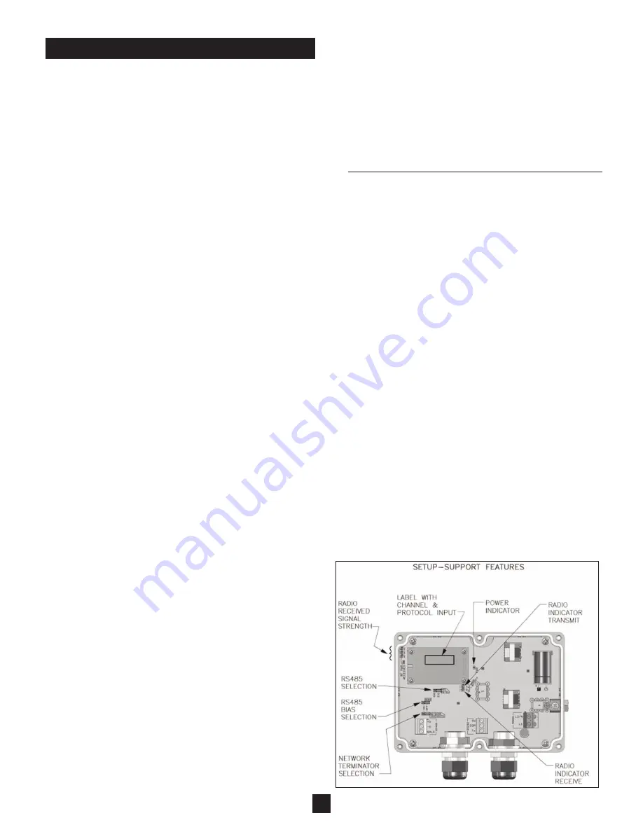
4) RS-485 load:
(See Figure 9) This selection is used
to terminate the RS-485 link to achieve maximum
communication reliability. If no RS-485 communica-
tions is to be used, simply turn “OFF” this selection.
If there is to be RS485 communications, then you must
determine if the
Wireless
EZ
Communication Interface
is physically on the end of the RS-485 wiring circuit.
If so, then the load selector should be turned “ON”. If the
Wireless
EZ
Communication Interface is not at the end
of the wiring circuit (i.e. two wire pairs branch off in two
different directions) then this selector should be turned
“OFF”. This evaluation should be conducted for every
device on the RS-485 network.
5)
Silo
Track
Timeout:
When using the
Wireless
EZ
Communciation module with
Silo
Track
, Inventory
Monitoring Software,the
Silo
Track
“Timeout” must be
set for 200ms. Time out is defined as the amount of
time between each sensor query by
Silo
Track
. The
default for
Silo
Track
is 100ms. To accommodate the
time required for the “radio link”, change registry setting
to 200ms as follows on Windows-based PCs:
For Current Windows Supported Operating Systems
a)
Press the Windows button and “R” key
simultaneously to open RUN window
b)
Type in regedit then click OK,
Click on: Computer
g
HKEY_LOCAL_MACHINE
g
Software
g
Wow6432Node
g
Monitor
Technologies
g
STComDriver
g
Communication.
When you click on “Communication” a
list will open up on the screen adjacent to the
registry directory tree. Double click on the
Timeout entry. Enter Value Data to 200 and select
Decimal.
c)
OK
d)
Close registry window
e)
Restart PC.
Indicators:
(See Figure 10)
(Three provided for reporting status)
1) Power:
The green POWER indicator will light
when power is applied to the unit.
2) Tx:
The Orange Tx (Transmit Data) light strobes when
the
Wireless
EZ
Communication Interface is transmit-
ting data to the other side of the wireless bridge.
3) Rx:
The Yellow Rx (Receive Data) light will strobe when
the
Wireless
EZ
Communication Interface receives data
from the other side of the wireless bridge.
LED Bar Graph-Received Signal Strength:
(See Figure 10)
There is a three LED signal strength “Bar Graph” located
on the left side of the PCB next to the RF Module. The bar
graph only works when the unit receives data from the
other
Wireless
EZ
Communication Interface. This will
occur when properly connected to a control device, such
as the
HMI
2
or
Silo
Track
PC Software, and will be accom-
panied by activity on the Rx indicator (Yellow).
The stronger the received signal, the more LED bars that
will illuminate.
Figure 10
7
(Tx)
(Rx)
Summary of Contents for WirelessEZ
Page 6: ...6 Figure 9...


