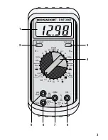
Please unfold page 3. Then you can always see the operating
elements and connections described.
Contents
1
Operating Elements and Connections . . . . . . . . . . . . . . . 12
2
Safety Notes . . . . . . . . . . . . . . . . . . . . . . . . . . . . . . . . . . 13
3
Applications . . . . . . . . . . . . . . . . . . . . . . . . . . . . . . . . . . . 13
4
Setting into Operation . . . . . . . . . . . . . . . . . . . . . . . . . . . 13
5
Carrying out Measurements . . . . . . . . . . . . . . . . . . . . . . 14
5.1
Voltage measurement . . . . . . . . . . . . . . . . . . . . . . . . . 14
5.2
Current measurement . . . . . . . . . . . . . . . . . . . . . . . . . 15
5.3
Resistance measurement and continuity test . . . . . . . 15
5.4
Diode test . . . . . . . . . . . . . . . . . . . . . . . . . . . . . . . . . . 16
6
Replacing of Battery or Fuse . . . . . . . . . . . . . . . . . . . . . . 17
7
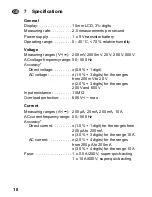
Specifications . . . . . . . . . . . . . . . . . . . . . . . . . . . . . . . . . . 18
1
Operating Elements and Connections
1 LCD display
2 Button “MAX HOLD” for “freezing” the maximum measuring
value in case of fluctuation of the displayed value
3 Button “DATA HOLD” for “freezing” a measuring value
4 Rotary switch for measuring range adjustment
5 Jack “µA mA” for the red test lead (positive pole) for current
measurements below 200 mA
6 Jack “10 A” for the red test lead (positive pole) for current
measurements from 200 mA to 10 A max.
7 Jack “COM” for the black test lead (negative pole)
8 Jack “V
Ω
” for the red test lead (positive pole) for voltage and
resistance measurements as well as for diode tests
GB
12


