


Device Description XVC-100
Text Display PLC
XVC-100
Commissioning
Subject to technical modifications
Doc No. 92 23 100000 (06/2002)
© by Moeller GmbH
27
Wiring instructions
The stations on the bus system are connected via fieldbus lines complying
with ISO 11898. The cables must accordingly have the following electrical
characteristics:
Parameter Abbreviation
Unit Value Value Value Note
min.
nom.
max.
Impedance Z
Ω
108
120
132
Measured between two
signal lines
Specific
resistance
m
Ω
/m
70
For the receiver
module, the differential
voltage on the bus
cable depends on cable
resistance between it
and the sender
Cable delay
ns/m
5
The mininum delay
between to points on
the bus is 0. The
maximum delay is
determined by the bit
timing and the delays of
the sender and receiver
circuits
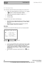
The figure shows the minimum wiring with shielding between two bus
stations with the Sub-D connector as an example. A bus terminating resistor
(120 Ohm between Pin 2 and Pin 7 of the Sub-D connector) must be
connected at the beginning and the end of each CAN bus. Do not swap
around the two signal wires!
Protective ground
Shield
Interface 1
Interface 2
Protective ground
For Immediate Delivery call KMParts.com at (866) 595-9616


