Programming through
CANopen network (routing)
02/05 AWB2724-1566GB
40
Notes
• If large files are written to the target PLC or read from the PLC,
it is possible that the online connection will be interrupted after
the transfer process has been completed. Renewed connection
is possible.
• If a program with a modified routing node ID is loaded into the
target PLC, the target PLC accepts the modified routing node ID;
however, the communication connection will be interrupted.
Reconnection with a corrected routing node ID is possible.
• If a PLC receives a program without valid routing parameters
(baud rate/node ID), this PLC cannot be connected via a routing
connection.
• The routing is independent of the configuration (master/slave):
a target PLC that has not been configured as a master or as a
slave can be accessed. It must only receive the basic parameters
such as node ID and baud rate, as well as a simple program.
Addressing
PLCs on the CANopen bus can be configured as a master or as a
slave. The PLCs are assigned with a node ID/node number
(address) in order to uniquely identify them. To use the routing
function to access a target PLC, you must assign a further node ID
to the PLC.
Procedure
X
Connect the PC to a PLC.
X
Select the target PLC with which you want to communicate for
the project.
X
Determine the communication settings for the PC and the PLC
connected to the PC.
X
Enter the target PLC’s target ID (target ID = node ID!) as shown
in the example and log on.
You can run the following functions:
• Program download
• Online modification
• Program test (Debugging)
• Create bootable project
• Filing source code.
Note for project creation:
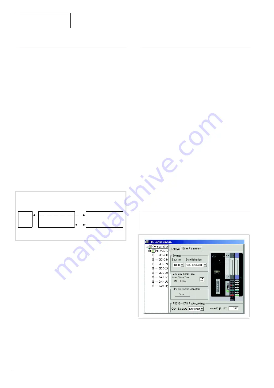
The node ID/node number and the baud rate of the target PLC to
the routing function can be defined in the
Additional
parameters
tab in the
PLC Configuration
window:
Enter the baud rate on the CANopen bus and the Node-ID/node
number in the “RS232
l
CAN routing settings” field.
This field appears with the XC200, after you have confirmed it in
the
Activate
field. This activation is necessary to ensure that the
PLC can communicate via the CANopen bus.
Node ID and baud rate are transferred with the project download.
The following illustrations indicate – independently of the routing
settings – where the baud rate and the node ID of the PLCs which
have been configured as masters or devices are to be entered. The
settings are to made in the master PLC in the
CAN Parameters
tab or with the device PLC in the
CAN Settings
tab.
Figure 66:XC100/200, XN-PLC on the CANopen bus, routing
principle
1) The following applies for the node ID of the device function and the
routing function:
– XC100 with operating system < V2.0 or XC200:
The routing node ID must be
not equal to
the device node ID.
– XC100 with operating system
f
V2.0 or XN-PLC:
The routing node ID must be
equal to
the device node ID.
PC
Routing PLC XC100/
200/XN-PLC
(master/device)
Node ID 1
Target PLC
XC100/200/XN-PLC
(device)
Routing node ID n
1)
Node ID n
1)
CANopen
h
To guarantee a fast data transfer, the routing should be
performed only with a CANopen baud rate of at least
125 Kbit/s.
Figure 67:CANopen routing settings
Summary of Contents for XION-PLC-CANopen
Page 4: ...2 ...
Page 8: ...02 05 AWB2724 1566D 4 ...
Page 10: ...02 05 AWB2724 1566GB 6 ...
Page 16: ...02 05 AWB2724 1566GB 12 ...
Page 18: ...02 05 AWB2724 1566GB 14 ...
Page 34: ...02 05 AWB2724 1566GB 30 ...
Page 38: ...02 05 AWB2724 1566GB 34 ...
Page 42: ...02 05 AWB2724 1566GB 38 ...
Page 48: ...02 05 AWB2724 1566GB 44 ...
Page 49: ...02 05 AWB2724 1566GB 45 Appendix Dimensions 113 25 114 75 50 6 74 4 ...


