Modern Forms retains the right to modify the design of our products at any time as part of the company’s continuous improvement program.
2
www.modernforms.com
XF-SCK
3. INSTALLATION INSTRUCTIONS
CAUTION:
To prevent electrical shock, ensure electricity has been
turned off at the circuit breaker.
NOTE:
This unit accommodates slopes of up to 45°.
1.
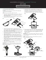
Remove the 2 canopy mounting screws and washers
180 degrees
apart on the outside edge of the mounting plate. Loosen the 2
remaining screws (Fig. 1).
2.
Install mounting plate to outlet box using the screws and washers
provided with your outlet box (Fig. 2).
Fig. 5
Outlet Box
Mounting Plate
Washers
Screws
Fig. 3
Fig. 4
Cross Pin
Set Screw
3.
Remove the hanger ball that was supplied with your fan by
removing the set screw. Slide the hanger ball off the downrod. Be
sure to keep the cross pin supplied with your fan’s downrod to use
with the slope ceiling adapter ball (Fig. 3).
4.
Follow the steps from your fan’s installation instructions to install
the downrod and coupling cover to the fan motor assembly.
5.
Feed motor lead wires and safety cable through the canopy of the
sloped ceiling kit (Fig. 4).
6.
Loosen the 2 set screws on the hanger ball provided with the
sloped ceiling kit and install it onto the downrod with the cross pin
removed in step 3. Push the hanger ball up until it engages the
cross pin and tighten the 2 screws on the hanger ball, securing it to
the downrod (Fig. 3).
7.
Carefully hang fan onto hook in mounting plate using one of the
2 holes in the canopy. This will allow hands-free wiring. Refer
to “Making the Electrical Connections” in your fan’s installation
instructions (Fig. 5).
8.
Make sure the flat side of the receiver is facing the ceiling before
attaching fan to mounting plate (Fig. 6).
WARNING:
Check to see that all connections are tight, including
ground, and that no bare wires are visible at the plastic wire nuts
except for the ground wires.
9.
Carefully lift fan from mounting plate hook, making sure not to
break any wire connections. The canopy has 2 mating slots and
2 mating holes. Position both slots in canopy directly under and
in line with 2 mounting plate screws and washers. Lift fan until
mounting plate screws are seated in bottom slots of canopy (Fig. 6).
10.
Rotate canopy clockwise until both mounting screws drop into slot
recesses. Tighten screws securely. Install screws and washers that
were previously removed in step 1 into mating holes and tighten.
Make sure that the tab in the canopy engages the notch in the
hanger ball (Fig. 6).
WARNING:
Failure to properly install and/or tighten the screws could
result in the fan loosening and possibly falling. Take care to make sure
all screws are tight.
NOTE:
Follow the steps from your fan’s installation instructions to
complete installation of your fan.
Screws
Receiver
Ta
b
Hanger
Ball Notch
Mating
Holes
Mating
Slots
Fig. 6
INSTALLATION INSTRUCTIONS
Fig. 2
Fig. 1
Screw


