background image


15 

overflows  in  the  overflow  pipe  of  the  pressure  vessel.  Installations  operating 
without losses may be supplied with raw water, provided that its hardness does 
not exceed 10n. Otherwise water shall be pre-treated. 

Install boiler accessories (handles and Bakelite knobs). 


2.5. Protection of the installation 


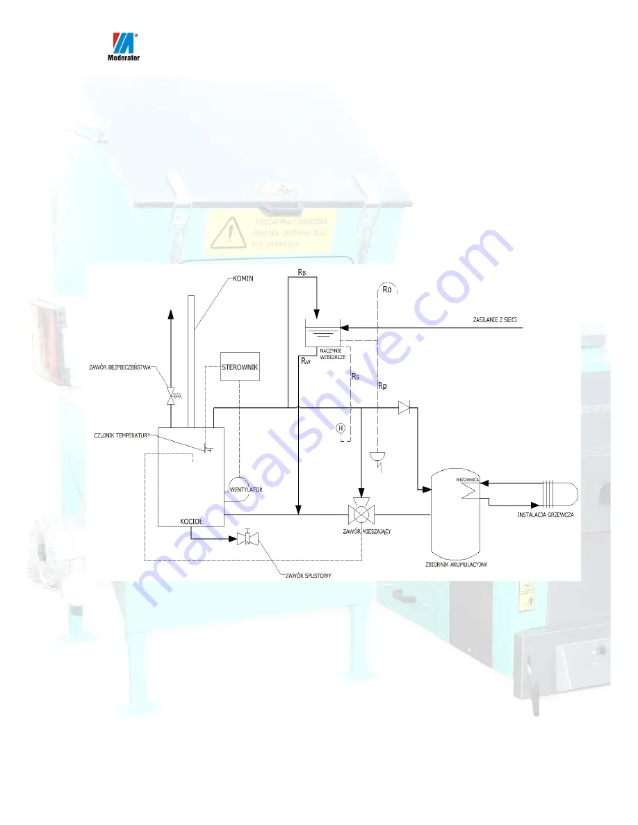
2.5.1. An open system 


Moderator  boilers  operating  in  open  central  heating  systems  must  be 

connected  according  to  requirements  of  the  PN-91/B-02413  standard,  so  that 
excess heat in the form of steam shall be removed through an open connection 
(RP overflow pipe) to atmosphere.  


KOMIN – CHIMNEY  


ZAWÓR BEZPIECZE

Ń

STWA - SAFETY VALVE 

CZUJNIK TEMPERATURY – TEMPERATURE SENSOR 

KOCIOŁ – BOILER 

STEROWNIK – CONTROLLER 


WENTYLATOR – BLOWER 

ZAWÓR SPUSTOWY – DRAINAGE VALVE 


NACZYNIE WZBIORCZE – PRESSURE VESSEL 

ZAWÓR MIESZAJ

Ą

CY– MIXING VALVE 


ZBIORNIK AKUMULACYJNY – HEAT ACCUMULATION TANK 

W

ĘŻ

OWNICA - COIL  


INSTALACJA GRZEWCZA – HEATING INSTALLATION 

ZASILANIE Z SIECI - WATER PIPE SUPPLY  

 
Fig.  4  Diagram  of  installation  protection for  boilers  operated in  open  central-
heating installations

.


Summary of Contents for Smok DTR-AZSB-30

Page 1: ...Operating Instructions Smok 30 240kW Automatic Biomass Burning Set ...

Page 2: ...ription of control box 20 2 6 2 Control Box Installation 20 2 6 3 Electric connections 22 3 Device Operation 31 3 1 Technical Description 31 3 2 Working Settings 32 3 3 Burning 33 3 3 1 Ignition 33 3 3 2 Continuous operation mode 34 3 3 3 Emergency operation of the boiler 35 3 4 Cleaning Ashes 36 3 5 Program Initiated Shutdown of AZSB 38 3 6 Emergency Shutdown of AZSB 38 4 Troubleshooting Safe Ope...

Page 3: ... installation operation maintenance and servicing It shall be read and understood before commencing with these activities 1 Overview 1 1 Safety Instructions The main condition of safe boiler operation is its correct connection to the central heating installation This will only be possible after all connection and operation requirements discussed in these instructions are met and complied with Fail...

Page 4: ... clean Fire safety leaving open covers or inspection holes or overfilling the container during burner operation may constitute an imminent fire threat Too much fuel in the container will prevent tight closing of the cover on each visit to the boiler room at last once per 12 24 hours it is necessary to check whether the fire water tank contains sufficient volume of water the recommended water volum...

Page 5: ...ler and systems may be hot Keep a safe distance This boiler may only be operated by people knowledgeable with the content of this instruction manual Do not stand on the housing The device may periodically switch on without warning Do not perform any works on a connected and switched on device The transport worm may start operating without warning Switch off power supply before lifting the cover Ro...

Page 6: ...an other parts of the boiler This also applies to smoke conduit and supply and return pipes When staying in the boiler room always stay alert Please note that ashes and fuel may cause allergic reactions Also during operation in the charging container carbon monoxide may accumulate We recommend wearing protective gloves and appropriate dust masks Remember to keep boiler room clean and in order Leav...

Page 7: ... by central heating installation freezing inoperable or obstructed combustion gases exhaust system shortage of water in the installation boiler application in uses other than specified in these operating instructions in case of incorrect selection of the boiler output to the heat demand of the object 6 All complaints shall be always filed to the boiler vendor Along with the complaint please provid...

Page 8: ...d Technical parameters of the device are specified for fuels with humidity content of up to 25 and calorific value of Q 16 862 kJ kg The higher the moisture content the lower the calorific value Increase of humidity causes drop of calorific value which means that one will need twice as much fuel to achieve the same heating effect A considerable part of thermal energy is wasted in the burning proce...

Page 9: ...isture content as well as during normal operation of the device Approximate data of different fuels parameters for a 30 kW device Time of 1 c m burning weight of 1 c m moisture content Fuel type h kg Bricks 96 260 10 Chips 36 155 25 Sawdust 24 145 25 Pellets 168 700 10 c m cubic meter 1 4 Technical Description The AZSB consists of a Moderator type boiler and Smok fuel feeder manufactured by Modera...

Page 10: ...ay be equipped with automatic ash removal system 1 Ignition doors 2 Ash pan doors 3 Air throttle 4 Upper washout holes cover 5 Smoke conduit 6 Thermometer 7 Supply pipe 8 Head plug 9 Thermal protection sensor G1 2 muff 10 Ash pan washout 11 Return pipe 12 Safety valve 13 G 1 2 muff for thermostat Fig 1 Moderator type boiler version designed for use in ABB set main parts 2 1 3 4 8 5 7 12 11 10 6 13...

Page 11: ...ead for humidity of up to 25 or ceramic head 20 40 Cast iron head Fig 2 is located inside the boiler combustion chamber The head operating principle is the following Fuel from the container 1 is transported to the head by a worm shaft meshed with mixers toothed wheels Fuel is fed to the head grate where in very high temperature using air supplied by the blower combustion process takes place Fresh ...

Page 12: ...Ceramic head 7 Blower 8 Head washout 9 Maintenance peephole 10 Supply pipe with bee wax plug 11 Fire water tank 12 Main control box 13 Fixing screw Fig 3 Ceramic head set Containers AZSB may include containers with varying volume between 0 6m3 and 10m3 The container is made of stainless steel sheet metal plates and on its bottom a set of mixing wheels coupled with the worm shaft is installed The s...

Page 13: ...ure 70 C Minimum recommended return temperature 55 C Operating pressure 1 5 bar for versions above 50kW 2 5 bar Thermal efficiency 84 Combustion gases minimum temperature 150ºC 2 2 Boiler Room The boiler room shall meet requirements of the PN 87 B 02411 standard Here are some of the most important of them waterproof flooring steel or wooden doors lined with sheet metal opening outwards 21x21 cm ai...

Page 14: ... the side panel of the fuel container Bottom of the water tank shall be at least 50 cm above the upper surface of the supply pipe Check that water hose is not bent or twisted 4 Make sure you have appropriate tools necessary to commence with installation a complete set of keys Installation identification of parts according to fig 2 or 3 1 Bolt the work shaft casing on to do the container 2 Slide in...

Page 15: ...inside the combustion chamber will be sufficiently high which means that the supply water on the boiler output shall have the temperature in the range of 70 to 800 C and that the water on return not less than 550 C Such operating parameters will protect the boiler against low temperature material corrosion In order to ensure correct operation of the boiler the manufacturer recommends installation ...

Page 16: ...ents of the PN 91 B 02413 standard so that excess heat in the form of steam shall be removed through an open connection RP overflow pipe to atmosphere KOMIN CHIMNEY ZAWÓR BEZPIECZEŃSTWA SAFETY VALVE CZUJNIK TEMPERATURY TEMPERATURE SENSOR KOCIOŁ BOILER STEROWNIK CONTROLLER WENTYLATOR BLOWER ZAWÓR SPUSTOWY DRAINAGE VALVE NACZYNIE WZBIORCZE PRESSURE VESSEL ZAWÓR MIESZAJĄCY MIXING VALVE ZBIORNIK AKUMU...

Page 17: ...ted against freezing 2 5 2 Closed Systems Moderator boilers operating in closed systems must be equipped with air supply system designed by Moderator Sp z o o for Moderator boilers we advise against installation of other air supply systems safety valve and additionally thermal protection permitting safe discharge of excessive thermal power Muffs welded in the upper jacket of the boiler are designe...

Page 18: ... of 95ºC Boiler installation without a reliable device to discharge the excessive thermal power is forbidden KOMIN CHIMNEY ZAWÓR BEZPIECZEŃSTWA SAFETY VALVE CZUJNIK ZAWORU TERMICZNEGO THERMAL PROTECTION VALVE SENSOR CZUJNIK TEMPERATURY TEMPERATURE SENSOR KOCIOŁ BOILER STEROWNIK CONTROLLER WENTYLATOR BLOWER ZAWÓR SPUSTOWY DRAINAGE VALVE ZABEZPIECZENIE TERMICZNE THERMAL PROTECTION ZAWÓR MIESZAJĄCY M...

Page 19: ... opens at 97O C After the ejection valve opens hot water flows out of the installation and cold water may flow in from the supply line this cools down the boiler When boiler temperature drops to 94O C the ejection valve closes Thermally controlled filling valve and temperature sensor help to restore the correct flow pressure in the heating installation When the temperature reaches 88 C also the fi...

Page 20: ... accessories are installed may only be opened by a qualified electric engineer knowledgeable with the device operation 7 Location of power receptacle used for the controller connection shall be chosen in such a way so that the power plug is readily accessible for quick disconnection in case of an emergency 8 Electric cables shall be well fixed on their whole length Wires shall be guided away from ...

Page 21: ...r maintenance purposes Below is the description of the control box installation procedure 1 Remove the ecoMAX800R control box from its packaging 2 Undo hooks 10 fig 6 and the front lid 1 fig 6 3 Using a flat screwdriver pry and remove 4 red plugs 10 fig 7 located in inner corners of the enclosure 4 Using a Ø8 mm drill bit drill holes in the plastic under removed plugs 1 2 3 6 7 8 4 9 5 10 1 Contro...

Page 22: ...evice Fig 7 Control box inside view Cables must not be guided through the control box enclosure without using cable glands The controller must not be installed on the boiler on the worm shaft pipe on flue ducts on the chimney nor on the fuel container or on any surfaces that may heat up above 50ºC 7 1 Motor switch aux connector 2 Motor switch 3 Feeder contactor 4 Controller output module 5 Fuse 6 ...

Page 23: ...300 300V 3x0 75 mm2 Blower H03VV F 300 300V 3x0 75 mm2 Central Heating Pump H03VV F 300 300V 3x0 75 mm2 Hot Water Pump H03VV F 300 300V 3x0 75 mm2 Ash removal option H03VV F 300 300V 3x0 75 mm2 Mixing valve actuator H03VV F 300 300V 4x0 75 mm2 Connections to outputs no 16 31 shall be made using the H03VV F 300 300V cable with cross section of 2X0 75MM2 APSB or AZSB devices cooperating with the con...

Page 24: ... fig 11a motors To connect the motor use a cable with the minimum cross section as specified in the table 1 Winding of the motor shall be connected in star to fig 11b The motor is supplied from the terminals of the 8 terminal strip fig 7 identified with the symbol shown on fig 11c The protective wire shall be connected to a terminal of the PE terminal strip 9 fig 7 Fig 11 a gear motor b motor conn...

Page 25: ... 8 3 1 1 5 3 4 3 8 If the protection switch is set incorrectly e g too high value then the device may get stuck which in turn may lead to motor overheating and burning or breaking the gear motor fixing Too low current may cause frequent trips of the switch Rated current values specified in the table 2 may actually slightly differ from those stated on the rating plate BLOWER The line that feeds the...

Page 26: ...the terminal identified as PE Remaining two lines are connected to terminals C and 2 If cables connected to terminals C and 2 are exchanged this will not affect the controller nor STB operation On the side of the controller the cable shall be connected to terminal strip 8 fig 7 terminals identified with the symbol shown on figure 15b The protective wire shall be connected to a terminal of the PE t...

Page 27: ...of the pump shall be made according to the pump manufacturer s technical documentation Fig 16 Identification of connecting terminals HOT WATER PUMP Hot water container pump shall be connected to terminal strip 8 fig 7 identified with the symbol shown on figure 17 The protective wire shall be connected to a terminal of the PE terminal strip 9 fig 7 The recommended cross section of the wire used for...

Page 28: ... 19 The protective wire shall be connected to a terminal of the PE terminal strip 9 fig 7 The recommended cross section of the actuator s connecting cable is stated in table 1 Fig 19 Identification of connecting terminals The actuator supports only mixing valve servos equipped with limit switches Use of other mixing valve servos is not allowed One may use actuators with the full rotation time betw...

Page 29: ...hand rather than using a key or a wrench Connect the sensor to terminals no 18 and 19 of the controller which are identified with the symbol as shown on fig 21 In order to extend the sensor cable one may use a cable with cross section stated in table 1 which does not exceed 10 m in length as this may adversely affect temperature readouts accuracy Installation of sensor cable along power supply lin...

Page 30: ...ensor cable along power supply lines shall be avoided It is necessary to maintain at least 10 cm spacing Fig 24 Identification of mixing valve temperature sensor connecting terminals In case of extended central heating systems with more than one mixing valve actuators it is possible to expand the controller with additional expansion module MX 01 which supports two mixing systems WEATHER SENSOR Thi...

Page 31: ...level sensor connecting terminals If the fuel level is exceeded the limit switch will trip The controller will stop feeding fuel to the burner head The fan will continue to operate The fuel will burn off and the fuel level will drop the limit switch will open and feeding will restart If the limit switch does not re close within 30 minutes a warning message HEAD FULL will be displayed The controlle...

Page 32: ...lame in the grate does not go out This is ensured by flame suspension function which remains active when the water in the central heating system meets preset values In the Run mode OPERATION the feed parameter feeding time operation sets the duration of the worm shaft feeder operation and the pause parameter feeding stop operation sets the duration of pauses between its activation When the water i...

Page 33: ...ontrol box settings despite the increase of the outdoor temperature The device must operate using both these modes The CONTROL mode must be initiated and last significantly longer than the OPERATION mode This will ensure appropriate head cooling If during operation user connects additional heat loads then the thermal power may be insufficient and in such case the system will only work in the OPERA...

Page 34: ...tion chamber manually after the mode is switched to LIGHT on the controller with the feeding being switched on When the fuel appears on the burner grate it shall be ignited and the blower shall be started using the blower fan switch After about 5 minutes the flame should stabilize Then one shall press EXIT and the controller will resume operation in automatic OPERATION mode If the fuel batch fed p...

Page 35: ...cumstances Sudden inflow of air may cause explosion Do not permit the head to work partially immersed in ash Poor cooling of the head may quickly lead to damage of its steel casing or cracking of grate plates During ceramic head operation washout under the head may require cleaning even as much as once per 2 days As the head is installed by the boiler the fuel may be periodically charged to the bo...

Page 36: ...nd protected by means of bolted steel flap In case of the ceramic head is not necessary to disconnect the feeder one however needs to protect the inlet to the head smoke conduit e g by covering it with a steel flap In case when the boiler is connected in a closed system it must not be used without manufacturer recommended protections see chapter 2 5 2 When igniting do not fill the whole combustion...

Page 37: ...wth of the air volume in the combustion chamber and explosive combustion of dusts When operating a boiler with air supply system do not open the charging flap during fan operation Before supplementing the fuel switch off the controller adjustment of the boiler performance and thus the supply water temperature shall be performed by changing the setting of the throttle or the ash pan doors adjustmen...

Page 38: ...all be cleaned before each heating season The Feeder For description of head cleaning see item 3 4 2 In case of the container it requires no maintenance during the heating season After the heating season s end it is necessary to disconnect the head from the boiler and to inspect the grate Remove deposit from cast iron elements check cast iron surfaces for cracks clean air inlet holes After cleanin...

Page 39: ...e fuel from the grate and move outside the boiler room lower circulating water temperature by adding cold water to the water charge like during filling maximally open the smoke conduit throttle if installed In case of boilers operating in closed system an emergency condition may be any condition resulting from power outage pumps stop or from leaving doors of the boiler open The central heating ins...

Page 40: ...ggles do not block charging flaps and ash pan doors grate change shall be performed using the ash pan lever use portable 24V lamps maintain order and cleanness in the boiler room maintain good technical condition of the boiler and its related installation during the winter season ensure that the heating process is continuous If water freezing in the installation is suspected check whether safety p...

Page 41: ...ed under the main pipe The mineral wool in such case is placed above the resistor We recommend to use automatic frost proof resistors which are available in multiple configurations Note Despite this effort in particular if wood chips are used as fuel the fuel may jam in the worm shaft Any remains shall be removed before the start of the heating season and at least once during the season If a water...

Page 42: ... pipe replace the bearing seal any leaks add oil replace the bearing remove the worm shaft remove the foreign body 6 Ceramic head Quick deposit build up Excessively fast lining wear Incorrect gassing process in the combustion chamber Smoke in the boiler room excessively contaminated fuel the head chamber has not been sufficiently pre heated the lining was damaged e g during cleaning too dry fuel u...

Page 43: ...Make sure that the device is really switched off If the boiler is in the flame suspend mode the blower and the worm shaft may not rotate for longer periods The device has stopped and has cooled down Boiler may have overheated causing the device to shut down Restart the controller The device has stopped display message BLOKADA PODAJNIKA feeder jam It is likely that a stone a root etc from peat or c...

Page 44: ...e to figures no 2 3 page 9 10 of the instructions 5 2 List of Wearable Parts No Part Name Part No 1 Door seals Z1 2 Ash container for versions from 100kW up Z2 3 Air supply control arm Z3 4 Ceramic head grate Z4 6 Cast iron head grate Z5 7 Safety valve fireman Z6 8 AZSB grate side 2 pcs Z7 9 AZSB grate bottom 1 pc Z8 NOTE The aforementioned parts are not subject to warranty replacement If their re...

Page 45: ...vided it is maintained operated and serviced properly shall reach several years 7 to 9 After that time it may be necessary to replace cast iron grate inserts if the repair is no longer economically reasonable the best way will be to dispose the head In case of the head the simplest way of disposing it is to send it to a metal specialized scrap metal collection plant ...

Reviews: