background image

R

www.quadrafi re.com

7033-277C

March 2, 2007

Tested and

Listed by

Beaverton

Oregon USA

OMNI- Test Laboratories, Inc.

C

US

DO NOT DISCARD THIS MANUAL

CAUTION

• 

Important operating 
a n d   m a i n t e n a n c e 
instructions included.

•  Leave this manual with 

party responsible for 
use and operation.

•  Read, understand and 

follow these instructions 
for safe installation and 
operation.

DO N

O

T

DIS

CA

RD

 WARNING

If the information in these instruc-
tions is not followed exactly, a 
fi re may result causing property 
damage, personal injury, or death.


•  Do not store or use gasoline or other fl am-

mable vapors and liquids in the vicinity of 
this or any other appliance.

•  Do not overfi re - If heater or chimney con-

nector glows, you are overfi ring. Overfi ring 
will void your warranty.

•  Comply with all minimum clearances to 

combustibles as specifi ed.  Failure to 
comply may cause house fi re.

HOT! DO NOT TOUCH

SEVERE BURNS MAY RESULT.
CLOTHING IGNITION MAY RESULT.

WARNING

•  Keep children away. 


•  CAREFULLY SUPERVISE children in same room as 

appliance.

•  Alert children and adults to hazards of high 

temperatures.

•  Do NOT operate with protective barriers removed or 

door open.

•  Keep clothing, furniture, draperies and other 

combustibles away. 

Glass and other surfaces are hot 
during operation and cool down.

Fire Risk.

WARNING

For use with solid wood fuel only.
Other fuels may overfi re and generate 
poisonous gases (i.e. carbon monoxide).

Installation and service of this appliance should 
be performed by qualifi ed personnel.  Hearth & 
Home Technologies recommends NFI certifi ed 
professionals, or technicians supervised by an 
NFI certifi ed professional.

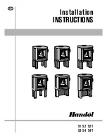
3100 WOOD STOVE SERIES

Advanced Combustion Control (ACC)

Owner’s Manual

Installation and Operation

Models: 

31M-ACC-MBK

31M-ACC-GT

31M-ACC-NT

31ST-ACC

Millennium Model

Step Top Uni-Body Model

(Pedestal Model Shown)

Summary of Contents for 31M-ACC-GT

Page 1: ... specified Failure to comply may cause house fire HOT DO NOT TOUCH SEVERE BURNS MAY RESULT CLOTHING IGNITION MAY RESULT WARNING Keep children away CAREFULLY SUPERVISE children in same room as appliance Alert children and adults to hazards of high temperatures Do NOT operate with protective barriers removed or door open Keep clothing furniture draperies and other combustibles away Glass and other s...

Page 2: ...ting beauty and enjoyment Our pledge to quality is completed as each model undergoes a quality control inspection From design to fabrication to shipping Our guarantee of quality is more than a word it s Quadra Fire tradition and we proudly back this tradition with a Lim ited Lifetime Warranty We wish you and your family many years of enjoyment in the warmth and comfort of your hearth appliance Tha...

Page 3: ...le 19 Section 6 Mobile Home 20 Section 7 Appliance Set Up A Pedestal Ash Removal System ARS Installation 21 22 B Leg Kit Ash Removal System ARS Installation 23 C Door Handle Assembly 24 D Blower Speed Adjustment 24 Section 8 Operating Instructions A Fire Safety 25 B Wood Selection Storage 25 C Burning Process 25 26 D Automatic Combustion Control ACC 26 E Air Controls 26 27 F Burn Rates Operating E...

Page 4: ...obile home and use only listed double wall connector pipe Outside Air Kit part OAK ACC must be installed in a mobile home installation B Mobile Home Approved EPA Certified 1 1 grams per hour Efficiency 79 51 BTU Output 11 800 to 32 000 Heating Capacity up to1 800 sq ft Vent Size 6 inches Firebox Size 2 cubic feet Max Wood Length 18 inches Fuel Cord Wood Shipping Weight 325 lbs Model 3100 Millenniu...

Page 5: ...nt of a chimney fire a Notify fire department b Prepare occupants for immediate evacuation c Close all openings into the stove d While awaiting fire department watch for ignition of adjacent combustibles from overheated stove pipe hot embers or sparks from the chimney WARNING Do NOT connect this unit to a chimney flue servicing another appliance Do NOT connect to any air distribution duct or syste...

Page 6: ...s to furnace or air condi tioning Imbalances of HVAC air handling system Upper level air leaks Recessed lighting Attic hatch opening Duct leaks To minimize the affects of negative air pressure the following must be considered Install the outside air kit Install the intake on the side of the house towards prevailing winds during the heating season Ensure adequate outdoor air is supplied for combus ...

Page 7: ...ce after one hour of operation at each burn setting NOTE These are guidelines only and may vary somewhat for individual installations F Tools And Supplies Needed Before beginning the installation be sure that the following tools and building supplies are available Reciprocating saw Pliers Hammer Phillips Head Screwdriver Flat Blade Screwdriver Plumb Line Level Tape Measure Framing Material Hi Temp...

Page 8: ...nation Cap Outside Air Rear Vent Spark Arrestor Cap Floor Protector Chimney Connector Ceiling Support Listed Chimney Listed Termination Cap Storm Collar Flashing Figure 8 3 Interior Prefabricated Chimney Figure 8 2 Exterior Prefabricated Chimney Figure 8 1 Masonry Chimney H Typical Stove Systems Stove system with masonry chimney consists of Stove Chimney Connector stove pipe Thimble Masonry Chimne...

Page 9: ...1 16 in 170mm 16 in 406mm 11 1 2 in 292mm 20 3 4 in 527mm C L A Appliance Dimensions Figure 9 1 Front View Figure 9 2 Side View NOTE Flue Collar size is 6 inch 152mm diameter ID 14 15 16 in 373mm 25 in 635mm 9 15 16 in 237mm 12 1 2 in 318mm 30 in 762mm 15 1 16 in 383mm 10 15 16 in 271mm 18 15 16 in 475mm C L Millennium Model ...

Page 10: ... 7 8 in 606mm 33 1 8 in 841mm 15 1 16 in 383mm 19 1 16 in 484mm 10 15 16 in 278mm 14 15 16 in 379mm 3 11 16 in 94mm 21 1 8 in 537mm 10 3 8 in 264mm Back of Stove to Glass 23 3 8 in 594mm 6 11 16 in 170mm 3 1 2 in 89mm C L 34 1 4 in 870mm 25 in 635mm 12 1 2 in 318mm 9 5 16 in 237mm C L 18 in 457mm 26 11 16 in 678mm 24 5 16 in 618mm 15 3 8 in 391mm 11 1 2 in 292mm 16 in 406mm 20 3 4 in 527mm ...

Page 11: ...Stove Through Backwall SINGLE WALL PIPE Flat Top Model 12 305 8 5 216 22 559 13 330 8 203 17 432 48 1220 12 305 Step Top Model 10 254 6 152 20 5 521 11 279 5 5 140 14 5 368 48 1220 12 305 DOUBLE WALL PIPE Flat Top Model 8 203 4 5 114 17 5 445 8 5 216 6 5 165 15 5 394 48 1220 9 229 Step Top Model 10 254 6 152 20 5 521 11 279 4 102 13 330 48 1220 9 229 INSTALLATION ALCOVE Six inch 6 152mm diameter l...

Page 12: ...tion 16 from glass 8 in USA Fuel loading door 4 7 8 in 3 1 8 in 31 5 8 in minimum 39 5 8 in minimum Must extend 2 in 51mm beyond each side of pipe shaded area CANADA 203mm 8 in 203mm 8 in 203mm 8 in 457mm 18 in 1260mm 49 5 8 in minimum 1041mm 41 in minimum In Canada similar floor protection must be provided 18 inches 457mm in front and 8 inches 203mm from the sides and rear of the stove See except...

Page 13: ...thick metal clad millboard or equivalent a minimum of 16 inches 406mm in front of glass and 8 inches 203mm to both sides of the fuel loading door Open the door and measure 8 inches 203mm from the side edge of the open ing in the face of the appliance See page 12 for Canadian clearances and horizontal venting exception For the Step Top Leg Model In US installations it is nec essary to install a flo...

Page 14: ...mes that have tightly sealed doors and windows an outside air source is needed An optional Outside Air Kit is available Flex Line Wire Tie Wire Tie Flex Adapter Terminatio Cap Remove circular knock out in base of pedestal WARNING Do not draw outside combustion air from Wall floor or ceiling cavity Enclosed space such as an attic or garage Close proximity to exhaust vents or chimneys Fumes or odor ...

Page 15: ...ppliance 4 Place the bracket containing the snap disc and magnet under the bottom left rear corner as shown in Figure 15 1 See page 29 for detailed operating instructions for the blower and snap disc Shock Risk Do NOT remove grounding prong from plug Plug directly into properly grounded 3 prong receptacle Route cord away from appliance Do NOT route cord under or in front of appliance CAUTION Figur...

Page 16: ...eel black or 26 gauge blued steel or an approved air insulated double wall venting pipe Thimble A manufactured or site constructed device installed in combustible walls through which the chimney connector passes to the chimney It is intended to keep the walls from igniting Site constructed thimbles must meet NFPA 211 Standards Prefabricated must be suitable for use with selected chimney and meet U...

Page 17: ...ming lumber to fit into wall opening Inside opening of frame should be no less than 14 inch x 14 inch 356mm x 356mm Figure 17 1 4 Attach the wall spacer to the chimney side of the frame 5 Nail the frame into the wall opening The spacer should be on the chimney side 6 Insert the section of the solid insulated chimney into the outer wall of the masonry chimney 7 Tightly secure the length of the soli...

Page 18: ...ctors must conform to each other to ensure a proper fit and seal Flue Gas Direction Crimped End Toward Stove Secure pipe sections with a minimum of 3 screws Figure 18 2 Chimney Connector Stove Pipe WARNING Do NOT connect this unit to a chimney flue servicing another appliance Do NOT connect to any air distribution duct or system May allow flue gases to enter the house Asphyxiation Risk Improper in...

Page 19: ...roof within 10 feet 305cm Must be located away from trees or other struc tures These are safety requirements and are not meant to assure proper flue draft Figure 19 1 E 2 10 3 Rule Figure 19 2 NOTE Chimney performance may vary Trees buildings roof lines and wind conditions affect performance Chimney height may need adjustment if smoking or overdraft occurs 3 ft 91cm Minimum Less than 10 ft 305cm 2...

Page 20: ...UL103 HT chimney and terminal cap with spark arrestor Never use a single wall connector stove pipe in a mobile home installation Use only double wall connector pipe Dura Vent DVL Selkirk metalbestos DS or Security DL double wall connector or any listed double wall connector pipe 5 In Canada this appliance must be connected to a 6 inch 152mm factory built chimney conforming to CAN ULC 629M STANDARD...

Page 21: ...uts and 2 bolts holding the grate in place and set the grate aside Discard the 2 nuts Install the gasket over the 4 protruding screws Figure 21 2 4 Install ash door assembly by sliding the rod at an angle into the slot on the left side and sliding over the 4 screws protruding from the bottom of the stove Secure with nuts provided Figure 21 2 5 Install magnet using a Phillips head screw driver This...

Page 22: ...stove Set the grate into the ARS channel and secure with 2 bolts previously removed Replace the 2 front cut bricks Figure 22 2 2 Install the ash drawer 3 Check to make sure baffle boards and ceramic blanket are in their proper locations see page 28 NOTE If installing a floor installation of an outside air kit on a Step Top model with a pedestal assembly you must attach the enclosed cover plate to ...

Page 23: ...you can slide the ash pan assembly bottom slots over the screw heads This allows the weight of the ash pan to rest on the screws while you are attaching the top 2 screws Once the ash pan is attached tighten all screws 3 Loosely assemble bolts into the corner of the mounting brack ets for leg attachment 4 Slide legs onto mounting brackets and tighten Make sure the legs are up against the bracket Th...

Page 24: ... blower and counterclockwise to increase the speed The blower speed control for this unit is adjusted at the factory and normally does not require further adjustment D Adjusting The Blower Speed Control C Door Handle Assembly 1 Install washer on door handle shaft 2 Slide door handle through door 3 Install second washer s as shown 4 Install key in groove 5 Align groove in latch cam with key slide l...

Page 25: ... to understand what goes on inside a stove The first stage of burning is called the kindling stage In this stage the wood is heated to a temperature high enough to evaporate the moisture which is present in all wood The wood will reach the boiling point of water 212 F and will not get any hotter until the water is evaporated This process takes heat from the coals and tends to cool the appliance Fi...

Page 26: ...s function is performed by sliding the con trol all the way back until it stops at the HI indicator on the label and then pulling forward to the front of the stove until it stops This activates the ACC system and opens the front air channel and allows air to enter the front of the stove for approximately 25 minutes The front air channel gradually shuts down until it is completely closed at the end...

Page 27: ...his air is regulated by the Burn RateAir Control There are four settings High Medium High Medium Low and Low When the control is raised all the way up it is on the High setting and when pushed all the down it is on the Low setting Figure 27 1 NOTE These are approximate settings and will vary with type of wood or chimney draft Due to altitude and other environmental circumstances this operational i...

Page 28: ...nce NEVER light or rekindle fire with kerosene gasoline or charcoal lighter fluid the results can be fatal 6 Once the kindling is burning quickly add several full length logs 3 inches 76mm or 4 inches 102mm in diameter Be careful not to smother the fire Stack the pieces of wood carefully near enough to keep each other hot but far enough away from each other to allow adequate air flow between them ...

Page 29: ... on and when your stove has cooled down to a certain temperature it will turn off NOTE The blower can still be left on at all burn rates even if you have deactivated the snap disc with the manual over ride knob See page 15 2 The blower is equipped with a speed control Adjust the fan speed by turning the speed control clockwise to Low or counterclockwise to High 3 Snap Disc Location If you find the...

Page 30: ...the paint and the burning off of any oils remaining from manufacturing Metallic noise Noise is caused by metal expanding and contracting as it heats up and cools down similar to the sound produced by a furnace or heating duct This noise does not affect the operation or longevity of the appliance Whirring sound If the optional blower has been installed the blower produces a whirring sound which inc...

Page 31: ...3 Disposal of Ashes 1 The stove and ashes must be completely cooled down before using the Ash Removal System Reach down and locate the ash removal door handle under the left side of the stove in the center Squeeze the handle and push all the way back Amagnet will hold the handle in place which in turn holds the ash door open 2 Clean ash down through the ash removal system grate into the drawer bel...

Page 32: ...r to your dealer for replacement of glass before further use Handle glass assembly with care When cleaning glass Avoid striking scratching or slamming glass Do NOT clean glass when hot CAUTION Do NOT use abrasive cleaners Use a hard water deposit glass cleaner on white film Use commerical oven cleaner on heavier deposits Remove all residue of oven cleaner or will permanently stain glass on next fi...

Page 33: ...clips on side of firebox and push the bottom of the brick until it is flush with the side of the unit C Firebrick Replacement Use Part 832 0550 when ordering individual brick Provide brick dimension or copy this page mark the desired brick and take it to your authorized dealer No Brick Size Qty 1 9 x 4 1 2 x 1 1 4 12 2 6 x 4 1 2 4 3 9 x 4 1 2 with angle 1 4 9 x 3 with angle 1 1 1 1 1 1 1 1 1 1 2 2...

Page 34: ...ace on top of baffle board open up and flatten and smooth out the blanket Re check the baffle board for correct positioning Figure 34 2 Figure 34 1 Baffle Figure 34 2 Ceramic Blanket E Snap Disc Replacement Magnet Spade Connectors Snap Disc Figure 34 3 1 Locate the snap disc bracket assembly at the bottom left rear corner of the stove Figure 34 3 2 A magnet holds the bracket to the stove Pull the ...

Page 35: ...e channel assembly into side of firebox and insert each tube into the corresponding hole in the tube channel rack starting with the back hole first 2 Make sure tube channel assembly is flush against the side of the stove and secure with channel nuts 3 Re install channel cover and side shield Channel Access Cover Channel Nuts 2 Side Panel Tube Channel Assembly Channel Cover Screws 4 Tube Channel Ra...

Page 36: ...re smoke in the house Obstruction in chimney Downdraft from chimney tem perature or from negative house pressure Have chimney checked if it workd previously Pre warm chimney Shut off exhaust devices Open window slightly Does the kindling wood not ignite Condition amount arrangement of kindling and fuel Use more drier well spaced kindling and fuel Does the kindling ignite but the fuel doesn t Amoun...

Page 37: ...install a blower Snap disc may be faulty Replace snap disc How much heat ouput do you expect Unrealistic expectations Heat output too low for square foot age Replace appliance with one with greater heat output How are air controls set Operational problems Follow manufacturer s instructions 5 The wood burns too fast What can I do Diagnostic Question Possible Causes of Condition Solutions What is th...

Page 38: ...ring Handle 1 2 inch Gold 832 0620 Nickel 250 8330 42 Trim Ring for Door Trim Door Assembly only Gold 430 2682 Nickel 430 5340 41 Washer Spacing Qty 1 222 0010 Qty 3 832 0990 42 43 44 45 46 47 48 31 30 40 29 41 4 6 7 8 9 10 11 12 13 14 15 5 Item Description Part No 6 Air Control Rod Guide Start Up 7033 210 13 Burn Rate Air Control Assem bly 7033 023 7 Control Arm Assy Rear Air 7033 035 8 Control R...

Page 39: ...nel Convection 5 Magnet 22 Bracket Convection Mount 6 Air Control Rod Guide Start Up 23 Air Supply Back 7 Control Arm Assembly Rear Air 24 Flue Collar 8 Control Rod Timer 25 Panel Assembly Side Left 9 Timer Mechanical 26 Air Channel Assembly Rear 10 Timer Arm Assembly 27 Brick Set 11 Door Assembly Rear Air 28 Tube Support Rack 12 Gasket Front Rear Air Doors 29 Blanket Ceramic 13 Burn Rate Air Cont...

Page 40: ...n Rate Air Control Assembly 35 Pedestal Ash Removal System 14 Spring Handle 1 4 inch 36 Legs Queen Anne 15 Door Assembly Front Air 37 Ash Pan Ash Removal System 16 Label for Burn Rate Air Control 38 Bracket Leg Mount Right 17 Label for Start Up Air Control 39 Flue Collar 18 Panel Assembly Side Right 40 Cover Plate Ash Removal System 19 Tube Channel Access Cover Top 41 Brick Set 20 Tube Channel Ass...

Page 41: ...7033 210 37 Ash Pan Front Assembly Leg Step Top 7033 008 Ash Pan Pedestal 7033 010 Ash Pan Leg Step Top 7033 050 33 Baffle Fiberboard 2 pieces SRV7033 209 Blower Motor Only Replacement 812 4900 29 Blanket Ceramic 1 2 thick field cut to size 19 wide x 13 3 4 high 832 3390 Blower Control Box with Switch 7000 194 38 43 Bracket Leg Mount Left Right Set Step Top SRV7033 183 Bracket Snap Disc 7033 036 B...

Page 42: ...ly 7000 012 Glass Frame Set 4 pc 832 0350 30 Hinge Pins Gold 2 832 0250 30 Hinge Pins Nickel 2 430 5320 46 Key Cam Latch Door Handle 430 1151 4 Knob Start Up Air Control 7000 343 16 Label for Burn Rate Air Control 7033 160 17 Label for Start Up Air Control 7033 166 Latch Handle Assembly Ash Removal 7033 047 Logo Quadra Fire Gold 200 3180 Logo Quadra Fire Nickel 200 3240 5 Magnet for Snap Disc Brac...

Page 43: ... Spring Handle Door 1 2 Nickel 250 8330 10 Timer Arm Assembly ACC 7033 034 9 Timer Replacement ACC 480 1940 42 Trim Ring Door Gold 430 2682 42 Trim Ring Door Nickel 430 5340 1 Trim Oak Strips for Pedestal 2 832 0560 19 Tube Channel Access Cover Top 7033 237 20 Tube Channel Assembly Manifold Tubes SRV7033 023 28 Tube Support Rack 7033 148 41 Washer Spacing Door Handle Qty 1 222 0010 Qty 10 832 0990...

Page 44: ...Page 44 7033 277C March 2 2007 R 3100 Wood Stove Series ACC Date of Service Performed By Description of Service C Service And Maintenance Log ...

Page 45: ...March 2 2007 7033 277C Page 45 3100 Wood Stove Series ACC R D Homeowner s Notes ...

Page 46: ...Page 46 7033 277C March 2 2007 R 3100 Wood Stove Series ACC D Homeowner s Notes Cont d ...

Page 47: ...r Hearth Home Technologies discontinues the model and two 2 years for optional accessories Adjustments regular maintenance cleaning and temporary repairs do not qualify for a service call fee and will not be covered The replacement of consumer replaceable items and installation of upgraded component parts do not quality for a service call fee and will not be covered This limited Lifetime Warranty ...

Page 48: ..._ 3100 Wood Stove Series ACC This product may be covered by one or more of the following patents United States 4593510 4686807 4766876 4793322 4811534 5000162 5016609 5076254 5113843 5191877 5218953 5263471 5328356 5341794 5347983 5429495 5452708 5542407 5601073 5613487 5647340 5688568 5762062 5775408 5890485 5931661 5941237 5947112 5996575 6006743 6019099 6048195 6053165 6145502 6170481 6237588 6...

Reviews: