26
1
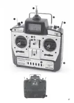
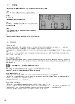
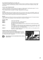
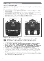
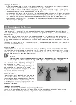
Transmitter antenna
2
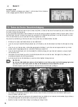
LC display
3
Rotary Controller 1
MODELS A & V: Travel limit for Function Channels 1, 2 & 4
4
Rotary Controller 2
MODEL A: Flaperon/fowler flaps
MODEL V: Aileron travel
MODELS H, C & C1: Pitch travel
For Aircraft Models H, C and C1, Rotary Controllers 1 and 2 can be used to adjust the pitch curve.
Both rotary controllers can be locked with the LOCK slide switch.
5
Toggle Switch 1
, Function Channel 5 (available) for supplementary functions
6
Toggle Switch2
(3D switch for aerobatics)
MODEL A: Simulaton of fowler flaps
MODEL V: Supplementary functions
MODELS H, C & C1: Idle running with the throttle/pitch control lever in mid-position
WARNING! When Models H, C or C1 are selected, you may only switch into 3D operation while the gas/pitch lever is in
the mid-position.
7
Toggle Switch 3
, dual-rate Function Channels 1, 2 & 4
Reduction of Functional Travels 1, 2 and 4 from 100% (Pos. 0) to 70% (Pos. 1)
8
„MODEL“ pushbutton
for selecting the aircraft model desired
9
LED (green)
indicates the switching status
10
LED (red)
indicates undervoltage
Replace the rechargeable batteries for the transmitter as soon as the red LED begins to blink, or when the LCD display goes off
at the very latest.
11
Remote control lever
(Function Channels 3 and 4)
12
Remote control lever
(Function Channels 2 and 1)
Both remote control levers can be extended by approx 5 mm.
13
Trim Function Channel 3
14
Trim Function Channel 4
15
Trim Function Channel 2
16
Trim Function Channel 1
17
Ring for carrying strap
18
On/Off switch
WARNING! With MODELS H, C or C1 are preselected, the 3D switch (Toggle Switch 2) has to be on „NOR“ when the transmitter
is switched on.
19
LOCK slide switch
for locking the rotary controllers and the MODEL pushbutton
20
Reverse switch,
Function Channels 1, 2, 3, 4 & 6
Bottom: NOR (normal), top: REV (reverse)
21
Handle
22
Transmitter quartz
23
Connector socket for flight simulator
24
(rechargeable) battery compartment
25
Charging socket
9. Transmitter controls

