background image

Product presentation

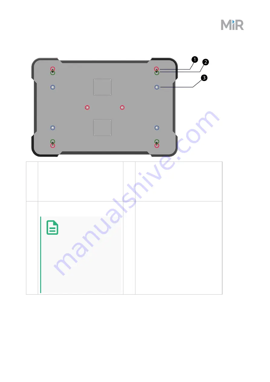
MiR500 top cover

View of MiR500 from the top:

1.

Not accessible; used for fixation of the
top cover.

3.

M10 mooring holes for fixation of top
module, e.g. MiR500 EU Pallet Lift or
MiR500 Lift.

Fore more information on mounting top
modules, see

Mounting a top module on

page 61

.

2.

M12 lifting holes; one in each corner used
for fixation of transportation eye bolts.

Note

M12 lifting holes can

also be used to mount

top modules. If a top

module is mounted

using these holes, it is

necessary to drill M12

lifting holes in the top

application in order to lift

the robot.

MiR500 user guide, 2019/03, rev.1.1

42

Summary of Contents for MiR500

Page 1: ...User guide MiR500 en Revision 1 1 Date 2019 03 ...

Page 2: ...nts of the document is subject to change without prior notice Every precaution has been taken in the preparation of this manual Nevertheless MiR assumes no responsibility for errors or omissions or any damages resulting from the use of the information contained Copyright 2017 2019 by Mobile Industrial Robots Contact the manufacturer Mobile Industrial Robots Emil Neckelmanns Vej 15F DK 5220 Odense ...

Page 3: ...lectrical outputs 11 2 10 Lithium battery 11 3 Getting started 12 3 1 In the box 13 3 2 Unpacking MiR500 13 4 Commissioning 16 4 1 Powering up 17 4 2 Connecting to the robot interface 18 4 3 Driving the robot in manual mode 19 4 4 Checking the hardware status 21 4 5 Charging the robot 21 4 6 Shutting down the robot 22 4 7 Creating and configuring a map 23 5 Planning 24 5 1 Analysis of the work env...

Page 4: ... 3 Side compartments 46 6 6 4 Top compartments 47 6 7 Sensor system 48 6 7 1 Safety laser scanners 48 6 7 2 3D cameras 51 6 7 3 Proximity sensors 54 6 7 4 Internal sensors 54 6 8 Light indicators 54 7 Maintenance 56 7 1 Regular weekly checks and maintenance tasks 57 7 2 Regular checks and replacements 57 7 3 Packing for transportation 59 7 3 1 Original packaging 59 7 3 2 Packing the robot for tran...

Page 5: ...et up and use MiR500 with MiR500 Lift MiR500 EU Pallet Lift Operating guide The operating guide that describes how to set up and use MiR500 with MiR500 EU Pallet Lift MiRCharge 500 Operating guide The operating guide that describes how to set up MiRCharge 500 and configure MiR500 for automatic battery charging at the charging station MiR Robot Interface 2 0 Reference Guide The reference that descr...

Page 6: ...nd brochures for MiR500 1 2 Document history This table shows latest and previous versions of this document and their interrelations with product software releases Revision Release date Description SW HW 1 0 2018 10 29 First edition 2 4 0 1 0 1 1 2019 01 31 New section Maintenance Updated styles 2 6 0 1 0 MiR500 user guide 2019 03 rev 1 1 4 ...

Page 7: ...not be held responsible for any damages caused to MiR500 accessories or any other equipment due to programming errors or malfunctioning of MiR500 The section contains the following topics 2 1 Safety message types 6 2 2 General safety precautions 6 2 3 Intended use 7 2 4 Foreseeable misuse 7 2 5 Risk assessment 8 2 6 Residual risks 8 2 7 Safety related functions and interfaces 9 2 8 Limiting safety...

Page 8: ...result in damage to equipment or property 2 2 General safety precautions This section contains general safety precautions WARNING If the load on the robot is not positioned or fastened correctly the load may fall or the robot may overturn Ensure that the load is positioned according to the specifications and fastened correctly See Payload specifications on page 63 WARNING Using a charger different...

Page 9: ...environments where access for the public is restricted For details about the environmental conditions in which the robot should operate see Technical specifications on our website MiR500 is equipped with special safety related features which are purposely designed for collaborative operation where the robot operates without fences and or together with humans MiR500 can be used with the lift module...

Page 10: ... to skid 2 5 Risk assessment One of the most important steps in achieving a safe installation is to make a risk assessment The risk assessment is the responsibility of the individuals who are commissioning MiR500 in the environment it will be used in Most often it will be an integrator who also designs and or builds work cells or other required infrastructure related to MiR500 The risk assessment ...

Page 11: ...ping by immediate removal of power to the machine actuators according to IEC 60204 1 followed by a controlled brake which brings MiR500 to a stop See Technical specifications on our website for more details Collision avoidance The collision avoidance safety function ensures that the robot will come to a stop before it collides with a human or object The function measures the speed on the two drivi...

Page 12: ...They are safe when low e g the emergency stop is not active when the signal is high 24V 2 9 1 Safety related electrical inputs This section contains the safety related electrical inputs of the robot External emergency stop button input This input is for connection of an optional emergency stop button If activated the safety system issues a category 0 stop followed by a controlled brake which bring...

Page 13: ...n will cause an emergency stop of both the robot and top manipulator Activated by an emergency stop button or emergency stop input 2 10 Lithium battery This section contains safety precautions related to lithium batteries in MiR robots WARNING Lithium battery packs may get hot explode or ignite and cause serious injury if they are abused electrically or mechanically Observe the following precautio...

Page 14: ...ting started 3 Getting started This section describes how to get started with MiR500 The section contains the following topics 3 1 In the box 13 3 2 Unpacking MiR500 13 MiR500 user guide 2019 03 rev 1 1 12 ...

Page 15: ...R500 User Guide MiR Robot Interface 2 0 Reference guide MiR robot REST API reference MiRCharge 500 Operating Guide MiR500 Lift Operating Guide MiR username and passwords CE declaration of conformity 3 2 Unpacking MiR500 This section describes how to unpack MiR500 Note Keep the original packaging for the future transportation of the robot 1 Place the box with the robot so that there is 3 m of free ...

Page 16: ...s of the box to the box lid and the base of the box 3 Remove the lid from the box 4 Take the folder with the printed documents and the USB drive out of the box 5 Remove the walls of the box and the protective foam blocks MiR500 user guide 2019 03 rev 1 1 14 ...

Page 17: ...raps 7 Place the lid of the box so that you can use it as a ramp Align the lid so that it is flush with the base of the box 8 Remove the wheel stop board from the pallet to let the robot drive on the ramp MiR500 user guide 2019 03 rev 1 1 15 ...

Page 18: ...ring up the robot The section contains the following topics 4 1 Powering up 17 4 2 Connecting to the robot interface 18 4 3 Driving the robot in manual mode 19 4 4 Checking the hardware status 21 4 5 Charging the robot 21 4 6 Shutting down the robot 22 4 7 Creating and configuring a map 23 MiR500 user guide 2019 03 rev 1 1 16 ...

Page 19: ...push two buttons on the hatch and pull the hatch 2 Turn the battery disconnect switch to position ON 3 The On Off button turns blue 4 Close the maintenance hatch 5 Ensure that all 4 emergency stop buttons are in the released state Turn an emergency stop button clockwise to release it MiR500 user guide 2019 03 rev 1 1 17 ...

Page 20: ...ready for operation the status lights turn constant yellow 4 2 Connecting to the robot interface When the robot is on it enables the connection to its WiFi access point The name of the access point appears in the list of available connections on your laptop tablet or a phone NOTICE The username and password for the robot s WiFi access point and for accessing the web interface are in the MiR userna...

Page 21: ...mat MiR_UXXXX 2 In a browser go to the address mir com and sign in 4 3 Driving the robot in manual mode To drive the robot in Manual mode 1 Put the Operating mode key into the Manual mode turn to the right 2 In the robot interface select the joystick icon The joystick control appears 3 Select Manual control The Restart button on the robot starts blinking MiR500 user guide 2019 03 rev 1 1 19 ...

Page 22: ...Commissioning 4 Press the Restart button The status lights turn blue indicating that the robot is in Manual mode 5 Drive the robot using the joystick MiR500 user guide 2019 03 rev 1 1 20 ...

Page 23: ... the OK status and that they have green dots on the left For more information see Hardware health in MiR Robot Interface 2 0 Reference Guide 4 5 Charging the robot Note A charger cable and an external charger is not part of the standard MiR500 delivery To charge MiR500 using the cable charger 1 Open the maintenance hatch at the back of the robot To open the hatch push two buttons on the hatch and ...

Page 24: ...uting an action 2 Press the On Off button for five seconds 3 The robot starts the shutdown process Status lights blink yellow the On Off button blinks red 4 When the robot finishes the shutdown process the status and the signal lights go off the On Off button turns blue If shutting the robot down for transportation or service repair the battery disconnect switch must be turned off as well and the ...

Page 25: ...ires a map to operate For information about creating a map refer to MiR Robot Interface 2 0 Reference Guide Section Creating an efficient map on page 29 describes how to make the map efficient and how to mitigate potential risks MiR500 user guide 2019 03 rev 1 1 23 ...

Page 26: ... training of the users will result in a successful and safe installation of MiR500 For more details on the topics below refer to the MiR Robot Interface 2 0 Reference Guide NOTICE Read section Safety on page 5 before going through this chapter The section contains the following topics 5 1 Analysis of the work environment 25 5 2 MiR500 user roles 27 5 3 Creating an efficient map 29 5 4 Creating eff...

Page 27: ...global planner that does the general path planning between two positions and a local planner that causes the robot to follow the global path and also take into account the surroundings so that the robot avoids dynamic obstacles based on sensor input MiR500 has two laser scanners that serve three main purposes Emergency stop the laser scanners trigger the emergency stop as part of the SICK Safety s...

Page 28: ... scanners of the robot will only detect parts of the chair Here the scanners detect the four legs of the chair in the upper left corner of the map The 3D camera will detect more details of the chair when it is close enough to it MiR500 user guide 2019 03 rev 1 1 26 ...

Page 29: ... if the robot is not running missions as it should Indirect user The indirect user of MiR500 could be someone working in the same environment as the robot but not working directly with the robot This user might need to change their work flow slightly for the company to make the most out of the robot For example if the user walks a certain path several times a day and this path crosses the robots p...

Page 30: ...t users are there What tasks do each user have with MiR500 What rights edit and control should the different users have What functions or widgets should be available for the different users For more details on interface and dashboards see MiR Robot Interface 2 0 Reference Guide 5 2 3 Training of the users It is very important to spend time on training the different users of MiR500 It is unlikely t...

Page 31: ...1 Use zones on the map Adding zones to the map can organize efficient robot traffic There are several different zones that can optimize the preferred paths and driving behavior of the robot For example a Forbidden zone is a zone where the robot will never enter A Blink or Light zone are zones where the robot either blinks or makes a sound to catch attention In a Preferred zone the robot tries to r...

Page 32: ...large highly dynamic area is an area where objects are moved frequently This could be a production area where pallets and boxes are often moved back and forth Issue MiR500 will always plan the shortest path from A to B If this is through a large highly dynamic area the robot will re plan its path several times The re planning happens because the robot will encounter new dynamic obstacles in the en...

Page 33: ... dangerous situations for the people working near the robot as they might be on the other side of the door and can not see the robot coming Issue The robot stops because a narrow doorway is seen as an obstacle Due to sensor input the robot will not plan a path through a narrow corridor if it has an alternative path The robot will always stop if a person steps out in front of it Solution Add a Crit...

Page 34: ... make a global plan underneath the shelves Solution Add a Forbidden zone marked red in the image around the shelves The shelves are marked as a Forbidden zone in the map Pallet rack When MiR500 docks to a pallet rack personnel detection means are temporarily muted This could cause a dangerous situation if a person steps in front of the robot and the pallet rack Issue MiR500 mutes the personnel det...

Page 35: ...issions include moving from point A to point B go to waiting position go to charge pick up pallet etc Missions within missions A good basis of different missions makes it possible to set up missions inside missions This way simple missions can be re used in different bigger and more complex missions 5 5 Error handling An error occurs when the robot is conflicted and cannot solve a situation on its...

Page 36: ... about MiR500 and its functions at a level that matches their user type direct indirect etc will help ensure a safe and successful installation of the robot Useful information at different levels could be Safety zones planning of paths and deviations from planned paths dynamic obstacles Illustrate that MiR500 will stop before driving into obstacles Daily weekly monthly cleaning maintenance and ins...

Page 37: ...ther possibilities they might find useful after having used the robot for some time This could include Sound and blink zones Preferred zones Directional zones Incorporation with other plant management systems such as ERP MiRFleet Rest calls Stay in contact It is important to stay in contact with the users after the installation of MiR500 Make sure to follow up with the following in mind If the cus...

Page 38: ...n be created or imported the first time the robot is used The internal map contains defined locations office product delivery production hall etc that are used for logistical planning While operating the safety laser scanners ensure that the robot avoids dynamic obstacles people furniture that are not mapped With a MiRCharge 500 the robot handles moving to a charging station automatically All it t...

Page 39: ...p to suit the different users Alert for lost If the robot enters a situation where it is unable to find a path to its destination it stops turns on the yellow purple running error light and a customer defined catch action may be used to alert people or take other actions Automatic deceleration for objects The built in sensors ensure that the robot is slowed down when obstacles are detected in fron...

Page 40: ...he identification label of MiR500 is placed above the MiR controller behind the rear maintenance hatch CE Mobile Industrial Robots ApS declares that MiR500 meets the requirements of the applicable EC directives Serial number The 15 digit serial number is a unique identifier of the robot The last four digits form part of the original name of the robot e g MiR U0008 MiR500 1 0 Product name and hardw...

Page 41: ...modes see MiR500 operating modes on the next page 6 3 2 The control panel buttons The buttons on the control panel have the following functions 1 Stop 3 On Off 2 Restart Stop Pressing the button stops the robot After pressing this button you must press the Restart button to let the robot continue operating Color indication Red The robot is on Restart Pressing this button Clears the emergency stop ...

Page 42: ... manual mode on page 19 Autonomous mode In this mode the robot executes the programmed mission After switching the key to this mode you can remove the key and the robot will continue driving autonomously The joystick is disabled in the robot interface 6 4 1 Muting of the personnel detection means When performing tasks that require to move very close to surrounding objects the robot mutes the perso...

Page 43: ...mergency stop 9 3D depth cameras two pcs detect objects in front of the robot see Sensor system on page 48 3 Signal light eight pcs two on each corner see Sensor system on page 48 10 Front maintenance hatch opens to front compartment see MiR500 internal parts on page 43 4 Rear maintenance hatch opens to rear compartment see MiR500 internal parts on page 43 11 Front safety laser scanner see Sensor ...

Page 44: ...t Fore more information on mounting top modules see Mounting a top module on page 61 2 M12 lifting holes one in each corner used for fixation of transportation eye bolts Note M12 lifting holes can also be used to mount top modules If a top module is mounted using these holes it is necessary to drill M12 lifting holes in the top application in order to lift the robot MiR500 user guide 2019 03 rev 1...

Page 45: ... Front compartment Rear compartment Side compartments Top compartments 6 6 1 Front compartment The front compartment holds the electronic components that may need regular service or replacement such as PC main control board and safety PLC To open the front compartment 1 Push the two white buttons and pull the hatch MiR500 user guide 2019 03 rev 1 1 43 ...

Page 46: ...ng underneath it and lifting slightly Front compartment components The front compartment contains the following components 1 Cable chain 6 Loudspeaker 2 Safe Torque Off contactors 7 Power board controlling power distribution for motor controller PC and safety PLC 3 Access point Router 8 Motor controller 4 Robot computer 9 Safety PLC 5 Buzzer MiR500 user guide 2019 03 rev 1 1 44 ...

Page 47: ...Product presentation 6 6 2 Rear compartment The rear compartment holds the robot s battery To open the rear compartment 1 Push the two white buttons 2 Pull the hatch MiR500 user guide 2019 03 rev 1 1 45 ...

Page 48: ...main power to the robot 3 Connector for status light band 7 Connection interface for MiR Controller 4 Brake release button shown in On position When turned off the brakes are released and the robot can be pushed manually 6 6 3 Side compartments The side compartments contain the right and left hand side bogies and drive wheels To open a side hatch turn the two screws 90 counterclockwise with a flat...

Page 49: ... status light band 2 Drive wheel 6 6 4 Top compartments The two top compartments hold interfaces to external units for example MiR500 EU Pallet Lift or MiR500 Lift To open a top compartment remove four screws and lift off the top cover The two top compartments contain interfaces for top applications and added safety functions MiR500 user guide 2019 03 rev 1 1 47 ...

Page 50: ...sors Safety laser scanners 3D cameras Proximity sensors Internal sensors 6 7 1 Safety laser scanners The safety laser scanners on MIR500 are of the type AOPDDR active opto electronic protective device responsive to diffuse reflection AOPDDR is a protective device that uses opto electronic transmission and reception elements to detect the reflection of the optical radiation generated by the protect...

Page 51: ...thereby avoiding collision with objects and people The safety laser scanners detect objects in a plane approximately 180 mm above ground Objects above or below are not detected by the safety laser scanners The two safety laser scanners together provide a full 360 view around the robot When in motion the safety laser scanners continuously scan the surroundings using a distance of up to 40 m while t...

Page 52: ...ile trying to avoid the obstacle If unable to make its way around the obstacle the robot stops and waits for clearance Protective fields The protective fields are part of the robot s personnel detection means The protective fields consist of individually configured contours The active protective field is automatically selected based on the speed of MiR500 A person or object within an active protec...

Page 53: ...ndards of MiR500 If they are changed Mobile Industrial Robots takes no responsibility for any safety related incidents and the warranty becomes void Muted personnel detection means When docking to pallet rack or a charging station the protective fields are muted to avoid unintended activation Muted protective fields is part of the drive mode Muted personnel detection means where the robot also slo...

Page 54: ...sed as 3D point cloud data They are not recording recognizable objects or people The following illustrations show the fields of view of the cameras The two 3D cameras can see objects up to 1700 mm above floor height MiR500 user guide 2019 03 rev 1 1 52 ...

Page 55: ...Product presentation The two 3D cameras have a horizontal field of view of 114 MiR500 user guide 2019 03 rev 1 1 53 ...

Page 56: ...sures the orientation and angular velocity of the robot Motor encoder Provides closed loop feedback signals by tracking the speed and or position of the motor shaft Accelerometer Measures non gravitational acceleration Wheel encoders Detect wheel movements 6 8 Light indicators The robot uses two types of light indicators to let people in the environment know what the robot is currently doing or pl...

Page 57: ...Signal lights are used to indicate the robot s immediate motion plans for example by signaling forwards backwards braking and left right turns The signal lights work similarly to lights used on cars white at the front red at the back and are used to indicate for example a left or right turn by blinking When the robot drives with muted personnel detection means for example when docking to a Pallet ...

Page 58: ...edures Note The stated intervals are indicative and depend on the operating environment and frequency of usage of the robot The section contains the following topics 7 1 Regular weekly checks and maintenance tasks 57 7 2 Regular checks and replacements 57 7 3 Packing for transportation 59 MiR500 user guide 2019 03 rev 1 1 56 ...

Page 59: ...le wheels Remove dirt with a damp cloth and make sure nothing is entangled in the wheels LED light band Check if the LED light band is intact Does the light show all the way around the robot Signal lights Check if the signal lights on the four corners blink and show correctly all the way around the robot 7 2 Regular checks and replacements Before starting replacement tasks that involve removal of ...

Page 60: ...SD tail To check the ESD tail open the left hand side maintenance hatch and make sure that the tail has contact with the ground Check every six months and replace as needed Broom front of robot Open the front maintenance hatch and remove the three screws to get to the broom If the charger pads are dirty or dusty check the broom Check every six months if the broom is intact Replace as needed 3D cam...

Page 61: ...pallet The lid of the box the ramp The walls of the box The wheel stop board Protective foam blocks Side blocks and the top layer Protective corner braces The braces prevent the robot from being damaged by the transport straps Screws 7 3 2 Packing the robot for transportation To pack the robot for transportation 1 Shut down the robot See section Shutting down the robot on page 22 2 Open the rear m...

Page 62: ...ou follow the safety precautions in this section and the instructions in section Packing for transportation on the previous page Different regulations apply depending on the mode of transportation Land sea or air Contact your distributor for more information CAUTION Lithium batteries are subject to special transportation regulations according to United Nations Regulation of Dangerous Goods UN 3171...

Page 63: ... four M10 holes for mounting top modules Tightening torque 47 Nm See MiR500 external parts on page 41 for more information on the mounting holes Mounting holes on the top of MiR500 CAUTION Certain top modules may require the installation of an extra emergency stop button Perform risk assessment according to standard ISO 12100 CAUTION Certain top modules may lead to new hazards and or increased ris...

Page 64: ...Applications CAUTION Stay within the specifications for weight and the payload s center of gravity see Payload specifications on page 63 MiR500 user guide 2019 03 rev 1 1 62 ...

Page 65: ...oad specifications The following drawings illustrate the center of mass CoM specifications for safe operation at different payloads The specifications apply to payloads of up to 500 kg Side view MiR500 user guide 2019 03 rev 1 1 63 ...

Page 66: ...Payload specifications Front view MiR500 user guide 2019 03 rev 1 1 64 ...

Page 67: ...Auxiliary Safety Functions To see the locations of the interfaces on the robot see section Top compartments on page 47 10 1 General purpose interfaces This section describes the general purpose interfaces located in the left hand side compartment on the top side of MiR500 Power An auxiliary power connection for top applications is provided in the top left hand side compartment See Connector list o...

Page 68: ...f a protective stop emergency stop Intended for high power loads like motors or actuators 4 GND Ground 5 24V 2A Always on when robot is on Intended for low power use like powering an external PLC 6 GND Ground 7 Unassigned Unassigned GPIO A GPIO connection is in the top left hand side compartment Pin numbers male connector viewed from the front left and wiring diagram right A variety of top applica...

Page 69: ...24V The following table contains the description of the pins of the GPIO interface Pin number Signal name Max current Description 1 O1 1A 24V Output 1 2 RTN Protected return 3 O2 1A 24V Output 2 4 RTN Protected return 5 O3 1A 24V Output 3 6 RTN Protected return 7 O4 1A 24V Output 4 8 RTN Protected return 9 I1 PNP Input 1 10 24V 1A 24V Protected output 11 I2 PNP Input 2 12 24V 1A 24V Protected outp...

Page 70: ...ection is in the top left hand side compartment Ethernet connection Pin numbers left and wiring diagram right The communication interface is 10 100 Mbit Ethernet using a M12 connector See Connector list on page 71 Various protocols can be supported e g Modbus The following table contains the description of the pins of the Ethernet interface Pin number Signal name 1 TX 2 RX 3 TX 4 RX MiR500 user gu...

Page 71: ...bers female connector viewed from the front left and wiring diagram right Auxiliary emergency stop is designed to support emergency stop and other safety functions The following table contains the description of the pins of the Auxiliary emergency stop interface Pin number Signal name Description 1 Test output 2 Test output 3 E stop 1 Emergency stop 1 4 E stop 2 Emergency stop 2 5 Reset 6 Safe RTN...

Page 72: ...n no reset is needed 4 Safeguarded stop 2 A low signal will result in the robot stopping and is not able to move until it is high again no reset is needed 5 Locomotion 1 Output high when the robot is standing still 6 Locomotion 2 Output high when the robot is standing still 7 Shared E stop out 1 Shared emergency stop out 1 Output low when the robot is in e stop 8 Shared E stop out 2 Shared emergen...

Page 73: ...eturn Ground 16 Unassigned Unassigned 17 Unassigned Unassigned 10 3 Connector list We recommend the following connectors for the five different interfaces Connector name Connector type Power M23 6p GPIO M17 17p Ethernet M12 4p Auxiliary Emergency Stop M17 8p Auxiliary Safety Functions M17 17p MiR500 user guide 2019 03 rev 1 1 71 ...

Reviews: