* In cases where valve pins are not numbered, use the position of the straight pin relative to the
other pins as shown in the pin layout to determine which pin is which.
1
GND
2
3
1
GND
2
3
1
2
GND
1
2
GND
1
2
GND
1
2
GND
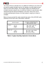
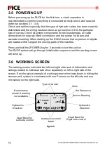
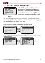
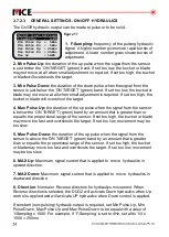
Table 2: Typical Hydraulic Cable Connections
Hydraulic Output
Type
Example Valves
Up Coil
Down Coil
Up Coil
Down Coil
Connections of A.RS.080
Bare Wires
(Wire Colour - Wire Label)
Valve Pin Layout*
PIN 1: Grey – VCC
PIN 2: Yellow – SIG1/UP1
PIN 3: Not Connected
GND: Pink - GND
PIN 1: Grey – VCC
PIN 2: Yellow – SIG1/UP1
GND: Pink - GND(Optional)
PIN 1: Green – VCC
PIN 2: Orange – DOWN1
GND: Not Connected
PIN 1: Orange – DOWN1
PIN 2: Yellow – SIG1/UP1
PIN 3: Not Connected
GND – Pink - GND
PIN 1: Pink – GND
PIN 2: Yellow – SIG1/UP1
GND - Pink-GND(Optional)
PIN 1: Pink – GND
PIN 2: Orange – DOWN1
GND: Not Connected
Danfoss PVG series
with PVE actuator
1) Eaton-Vickers
KDG4V series
(Current Proportional output)
2) Rexroth 4WE6
(On/Off Low Side output)
3) Eaton-Vickers
DG4V series (On/Off
Low Side output).
Note: The Rexroth 4WE6
and Eaton-Vickers DG4V
can also be driven with
On/Off High Side output if
wired as shown in On/Off
High Side below
1) Danfoss On/Off with
PVEO actuator
2) Rexroth 4WE6 series
3) Eaton - Vickers DG4V
series
Note: The Rexroth 4WE6
and Eaton - Vickers DG4V
can also be driven with
On/Off Low Side output if
wired as shown in On/Off
Side row above.
Voltage
Proportional
(V[O])
Current
Proportonal
(I[O]) or
On/Off Low Side
On/Off High Side


